background image

2-23 (E)

NSS-V2

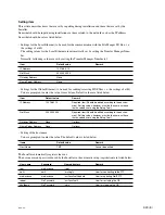
Setting item

This article describes items that are set by inputting during installation and those that are set by the
Installer.
Items that should be input during installation are those related to the network such as the IP address.
Items that should be set are listed below.

.

Settings for the Local Ethernet (to be used for the communication with the File Manger I/O Box, i.e.
the settings of eth0)
The setting values for the Local Ethernet are automatically set by setting the Transfer Manager Num-
ber.
Normally, following values are set by setting the Transfer Manager Number to 1.

Item

Default value

Remark

IP Address

192.168.0.10

Net Mask

255.255.255.0

Gateway Address

None

Name Server Address

None

.

Settings for the Global Ethernet (to be used for sending/receiving MXF files, i.e. the settings of eth1)
You are prompted to enter the value for each item. Default values are listed below.

Item

Default value

Remark

IP Address

192.168.1.10

Required item (Should be edited according to the environ-
ment. Setting values, however, must be the same as those
that have been set using the Setup Tool.)

Net Mask

255.255.255.0

Required item (Should be edited according to the environ-
ment. Setting values, however, must be the same as those
that have been set using the Setup Tool.)

Gateway Address

None

Optional

Name Server Address

None

Optional

.

Setting of the host name
You are prompted to enter the value. The default value is listed below.

Items

Default value

Remark

Host Name

TM1

Cannot be omitted

The Installer automatically registers the user.
The user names and passwords used by the Installer in the automatic setup (registration) are listed below.

User name

Password

Home directory

Remark

root

mediavenue

/root

_

netif

netif

/mnt/egfs

User for connecting to the FTP

mediavenue

mediavenue

/usr/local/netif/update

User for updating NetIF FTP

reboot

No Password

/usr/local/netif

User for restarting the OS

shutdown

No Password

/sbin

User for stopping the OS

Содержание NSS-V2

Страница 1: ...INSTALLATION MANUAL 1st Edition Revised 1 MULTI FORMAT MEDIA SERVER NSS V2 DIGITAL INPUT PROCESSOR BOARD BKNS V202 DIGITAL OUTPUT PROCESSOR BOARD BKNS V203 9PIN CONTROL INTERFACE BOARD BKNS V209 ...

Страница 2: ...ées dans le mode d emploi à moins d être qualifié pour en effectuer d autres Pour toute réparation faire appel à une personne compétente uniquement NSS V2 Serial No 10001 and Higher BKNS V202 Serial No 10001 and Higher BKNS V203 Serial No 10001 and Higher BKNS V209 Serial No 10001 and Higher WARNING This unit has no AC power switch When installing the unit incorporate a readily accessible disconne...

Страница 3: ...ed in a rack please make sure that the rack does not achieve hazardous condition due to uneven mechanical loading 5 Install the equipment while taking the operating temperature of the equipment into consideration For the operating temperature of the equipment refer to the specifications of the Operation Manual 6 When performing the installation keep the following space away from walls in order to ...

Страница 4: ...her Mount in a rack to avoid the risk of the unit sliding and causing injury Ground the unit safely Failure to ground the unit may cause electric shock Handling the unit by holding the designated positions When handling the unit be sure to hold the following positions Otherwise the unit may break and fall causing injury Rack angle Bottom case Especially do not hold the front panel or the handle of...

Страница 5: ...e Overview 2 1 Cleaning the Air Filter 2 1 E 2 2 Functional Descriptions of Board Switches and LEDs 2 2 E 2 2 1 FC 100 Board 2 2 E 2 2 2 SY 318 Board 2 3 E 2 2 3 TM 45 Board 2 4 E 2 2 4 MPU 136 Board 2 5 E 2 2 5 ENC 90 Board BKNS V202 2 6 E 2 2 6 DEC 154 Board BKNS V203 2 7 E 2 2 7 IF 972 Board BKNS V209 2 8 E 2 3 Operating Setup Tool 2 9 E 2 3 1 Setup Tool Descriptions 2 10 E 2 3 2 Changing Setup...

Страница 6: ......

Страница 7: ...r local Sony Sales Office Service Center Part number 9 968 190 XX Contents The following is a summary of all the section for understanding the contents of this manual Section 1 Installation Explains the operating conditions installation space power supply installation of option board rack mounting connection and checks after connection Section 2 Service Overview Explains the procedure for cleaning...

Страница 8: ......

Страница 9: ... prepared The personal computer for installing the File Manager software OS Red Hat Linux ES TimeSys Linux CPU Intel Xem 3 4 GHz or more Memory 2 GB or more HDD 36 GB or more Ethernet 100Base TX n For the newest information on the personal computer please contact your local Sony Sales Office Service Center Start Determination of Installation Space Rack Mounting Installation of Option Boards Connec...

Страница 10: ...midity 10 to 90 No condensation Mass NSS V2 Approx 21 kg BKNS V202 Approx 1 kg per one set BKNS V203 Approx 1 kg per one set BKNS V209 Approx 1 kg per one set To prevent overheating of the NSS V2 ensure that there is good air circulation around the unit w Do not install the unit in humid or dusty environment c Do not stack the units ...

Страница 11: ...s for ventilation and mainte nance Do not stop the fan or block the ventilatior because this unit is air cooled by the fan of the power supply If not a fire or failure may occur Unit mm MULTI FORMAT MEDIA SERVER NSS V2 1 2 3 4 5 6 7 8 9 10 POWER SYSTEM 37 113 3 231 115 5 310 72 8 440 420 3 457 3 31 5 440 390 4 465 482 101 6 176 195 1 ...

Страница 12: ...ible so that the user can turn off the power in case a fault should occur 2 1 AC inlet 2 1 AC inlet AC inlet 2 1 1 3 2 Recommended Power Cord Recommended parts For customers in the U S A and Canada 1 Power cord 125 V 10 A 2 4 m 1 551 812 31 2 Plug holder Brown 3 613 640 01 For customers in the United Kingdom 1 Power cord 250 V 10 A 2 4 m 1 551 631 61 2 Plug holder Brown 3 613 640 01 For customers ...

Страница 13: ...nt rail RMM 10 option Componets of RMM 10 Rack brackets 2 pcs Rack mounting adaptor right 1 pc Including two screws B4 x 6 7 682 560 09 Rack mounting adaptor left 1 pc Including two screws B4 x 6 7 682 560 09 Rack bracket fixing screws 6 pcs B4 x 6 7 682 560 09 Adaptor fixing screws B4 x 10 7 682 562 09 6 pcs Required other parts To mount the unit in the rack the following parts are required suppl...

Страница 14: ...re is case of left side 6 Fasten the length adjustment screws which are loos ened in step 4 B4 x 6 Adaptor Portion of the rail 4U 31 75 31 75 B4 x 10 B4 x 10 Unit mm 7 Align the crook of the each rack bracket on the side panels of the unit with the rail then slide the unit backward n Each rack bracket covers the rails as shown in the figure below 8 Fix the unit to the rack with the specified screw...

Страница 15: ...stallation procedure for the BKNS V202 is de scribed here as an example The installation procedure for the BKNS V203 is exactly the same 1 Turn off the power to the NSS V2 2 Remove the two fixing screws of the blank panel and draw out the blank panel by the handle n Be sure to store the removed blank panel 3 Insert the BKNS V202 ENC 90 board into the slot and securely connect it to the motherboard...

Страница 16: ...h the two screws that were fixing the blank panel of the NSS V2 Blank panel B3 x 6 handle IF 972 board The illustration shows the BKNS V209 handle handle B3 x 6 1 5 2 Installing the BKNS V209 General information for Installation The BKNS V209 can be installed while the NSS V2 is being powered m Install the BKNS V209 that connects the 9 pin controller to slot 10 See the panel display on the rear Wh...

Страница 17: ...ollows 100BASE TX 100BASE TX 8 pin Modular jack External view Pin No Signal 1 TX 2 TX _ 3 RX 4 5 NC 6 RX _ 7 8 NC 1 8 5 1 6 9 REMOTE RS 422A D sub 9 pin Female External View Pin No Signal 1 FRAME GND 2 TX _ 3 RX 4 GND 5 NC 6 GND 7 TX 8 RX _ 9 FRAME GND FIBRE CHANNEL LC connector External View Pin No Signal 1 TX 2 RX 1 2 ...

Страница 18: ...BNC 75 Z BNC 75 Z _ Belden 8281 cable 1 HD SDI IN BNC BNC 1 569 370 12 HD SDI OUT 1 2 5C FB cable 2 _ FIBRE CHANNEL LC connector Optical fiber cable with LC _ 1 2 3 4 connector Fiber classification GI 50 125 100BASE TX 8 pin modular jack RJ45 _ LOCAL 1 LOCAL 2 UTP 5 Unshielded Twisted Pair GLOBAL Category 5 cable REMOTE D sub 9 pin Female D sub 9 pin Male 1 560 651 00 Connector RCC 5G 10G 30G cabl...

Страница 19: ... Ethernet 1 Ethernet 1 Ethernet 2 Ethernet 2 REF VIDEO IN TC IN 9pin Controller Fibre Channel Switch File Manager PC Transfer Manager PC SDI OUT SDI IN TC IN REMOTE REMOTE 100BASE TX LOCAL 1 100BASE TX LOCAL 1 100BASE TX LOCAL 1 FC 2 FC 1 100BASE TX 1 100BASE TX LOCAL 1 Fibre Channel 1 Fibre Channel 2 TC IN REF VIDEO IN SDI OUT REMOTE 9pin Controller NSS V2 NSS V2 NSS S2 NSS S2 FC 1 100BASE TX 1 E...

Страница 20: ...witch on the SY 318 board chassis number setting Set the chassis number in order from 1 to the number of NSS V2 units to be used without duplication Setting example One NSS V2 unit 1 factory default setting Two NSS V2 units 1 2 Four NSS V2 units 1 2 3 4 Rear view ID switch SY 318 board 0 F E DCB A 9 8 7 6 5 4 3 2 1 ...

Страница 21: ...cumulated dust on the filter impedes the flow of air the inside may heat up and troubles may occur Clean the filter periodically Cleaning 1 Turn off the main power of the NSS V2 2 Fully loosen the two screws with drop safe and remove the front panel 3 Remove the filter in the direction of the arrow 4 Remove the dust from the filter using a vacuum 5 Attach the filter in reverse order of the disasse...

Страница 22: ...actory Use _ D110 H 1 _ _ D201 E 2 Green CONF DONE Lights when FPGA cofiguration is complete Lights on D401 to D408 F 4 _ _ Factory Use _ D409 G 2 _ _ D501 H 4 _ _ D502 H 4 _ _ D503 B 2 _ _ D505 B 1 _ _ D510 to D517 H 4 _ _ D700 to D708 E 3 _ _ D1000 Side B A 2 Green FC1 LINK Lights while receiving transmitting the data Lights on when FC1 when the link of FC1 is connected is used D1001 Side B A 3 ...

Страница 23: ...tion Factory setting S101 H 1 RESET Initializes the SY 318 board _ S102 H 1 _ Factory Use _ S501 H 4 _ Factory Use All OFF S711 A 4 ID SW Sets the shassis number of NSS V2 1 LEDs Ref No Address Indication Name Function Normal state color D101 H 1 _ _ Factory Use _ D110 H 1 _ _ D201 E 1 Green CONF DONE Lights when the FPGA cofiguration is Lights on complete D401 to D408 F 4 _ _ Factory Use _ D409 G...

Страница 24: ...onent side Switches Ref No Address Name Function Factory setting S101 E 1 RESET Initializes the TM 45 board _ S102 D 1 _ Factory use _ S501 G 3 _ Factory Use All OFF LEDs Ref No Address Indication Name Function Normal state color D110 F 1 _ _ Factory Use _ D201 D 1 Green CONF DONE Lights when the FPGA cofiguration is Lights on complete D401 to D408 F 3 _ _ Factory Use _ D409 G 3 _ _ D503 C 1 _ _ D...

Страница 25: ... D706 D707 D708 1 D601 D604 D603 D602 Side A component side Switches Ref No Address Name Function Factory setting S1 B 5 _ Factory Use _ S701 G 2 _ Factory Use All OFF LEDs Ref No Address Indication Name Function Normal state color D701 to 708 G 1 _ _ Factory Use _ D601 to 604 C 1 _ _ ON 1 2 3 4 5 6 7 8 ...

Страница 26: ...ng S101 J 1 RESET Initializes the ENC 90 board _ S102 J 1 _ Factory Use _ S501 K 4 _ Factory Use All OFF LEDs Ref No Address Indication Name Function Normal state color D101 K 1 _ _ Factory Use _ D110 J 1 _ _ D201 D 2 Green CONF DONE Lights when the FPGA cofiguration is Lights on complete D401 to D408 G 4 _ _ Factory Use _ D409 J 2 _ _ D501 K 4 _ _ D502 K 4 _ _ D503 A 2 Amber OPR Lights when the b...

Страница 27: ...ing S101 J 1 RESET Initializes the DEC 154 board _ S102 J 1 _ Factory Use _ S501 K 4 _ Factory Use All OFF LEDs Ref No Address Indication Name Function Normal state color D101 K 1 _ _ Factory Use _ D110 J 1 _ _ D201 D 1 Green CONF DONE Lights when the FPGA cofiguration is Lights on complete D401 to D408 H 4 _ _ Factory Use _ D409 H 2 _ _ D501 K 4 _ _ D502 K 4 _ _ D503 A 2 Amber OPR Lights when the...

Страница 28: ...2 8 E NSS V2 2 2 7 IF 972 Board BKNS V209 Side A component side D101 1 2 3 4 A B C D E F G H LEDs Ref No Address Indication Name Function Normal state color D101 H 1 _ _ Factory Use _ ...

Страница 29: ...nter key Space equivalent to a character Personal computer Use a personal computer of the following specifications OS Windows XP English or Japanese version Pointing device such as mouse RS 232C port Ethernet port Table of required files SetupTool exe Setup Table Update Version 1 3 23 or later Connection 1 Connect the PC to the global network of the system with the Ethernet cable Preparation 1 Cop...

Страница 30: ... expanded on Tool When a desired item in Basic Setup and a desired setup item in the list view of Detail Setup are clicked and then the Dynamic Setup button is clicked only the corre sponding setup value is reflected to FM Note that the items for which Dynamic Setup takes effect are limited Dynamic Setup is displayed as active only when the applicable items are clicked When FM is not running an er...

Страница 31: ...n ID of FM Password Password of FM 2 Local Settings Local folder where the Setup Table file is saved Help 1 Version Displays the Version screen 2 3 2 Changing Setup Table 1 Click the Get Setup button to download the setup conf file from FM 2 The current setup information is displayed 3 Change each setup item as necessary and click the Put Setup button 4 The changed items are displayed in red Confi...

Страница 32: ...e Dynamic Setup button is disabled 1 After the setup values are changed click the Dynamic Setup button with the changed item being selected 2 Repeat step 1 for other items to change setup values 3 When all changes are complete click the Put Set up button n The content of Setup Table setup conf is not changed only by clicking the Dynamic Setup button 4 The changed items are displayed in red Confirm...

Страница 33: ...ing NSS V2 units 1 2 Time Slot Cycle Specifies the time slot cycle 3000 ms 5000 ms Number of Net I F Specifies the number of the constituting BZN 202 units 0 1 FC Rate Specifies the fibre channel rate 2 G FC Mode Specifies the fibre channel mode Normal Ref Selects the REFERENCE input terminal SD SD Uses the reference video signal as a reference signal Inputs the video signal VBS with chroma burst ...

Страница 34: ... 0 Default Gateway for Global Network Sets the default gateway of the global interface of FM 0 0 0 0 Which Log Logs are categorized for every bit 0x00000001ffffff01 Sets whether or not to acquire the log IP Adress for TrapHost1 Sets the SNMP s Trap destination For one location 0 0 0 0 IP Adress for TrapHost2 Sets the SNMP s Trap destination For two locations 0 0 0 0 IP Adress for TrapHost3 Sets th...

Страница 35: ... not to acquire the log Which Log Port 2 Logs are categorized for every bit 0x08209101 Sets whether or not to acquire the log Which Log Port 3 Logs are categorized for every bit 0x08209101 Sets whether or not to acquire the log Which Log Port 4 Logs are categorized for every bit 0x08209101 Sets whether or not to acquire the log Which Log Port 5 Logs are categorized for every bit 0x08209101 Sets wh...

Страница 36: ...up to five lines from the codec compression of NSS V2 in each of the first field and the second field When Field Frequency of Basic Setup System Settings is set to NTSC the settings of NonCompression Line Fx x 525 are reflected In the case of PAL the settings of NonCompression Line Fx x 625 are reflected F1 x indicates the item that sets the lines to be excluded from compression in the first field...

Страница 37: ... Mark inserting position 17 Line Select from 11 Line to 19 Line Position SD PB UMID Essence Mark Sets the UMID and Essence Mark inserting position 17 Line Select from 9 Line to 20 Line Position HD ARIB Position SD Sets the ARIB inserting position 18 Line Select from 11 Line to 18 Line ARIB Position HD Sets the ARIB inserting position 19 Line Select from 9 Line to 19 Line PB VITC Position 1 525 Set...

Страница 38: ...stop script Network settings Network settings The network settings that are set using the installation steps described here and the names of correspond ing logical interfaces are shown in the following table Logical IF Type Default value IP address Subnet mask Default GW eth0 Local network 192 168 0 100 255 255 255 0 _ eth1 Global network 192 168 1 100 255 255 255 0 _ m The IP address of eth0 must...

Страница 39: ...alues n Be careful to enter the network settings since they are all cleared when reentering them 4 When installation and settings are completed the install CD ROM is ejected the server automatically restarts and the operating system and File Manager automatically starts 2 4 3 Others Starting Stopping File Manager Start command usr local edgestore run FM sh start File Manager is automatically start...

Страница 40: ...llowing command to forcibly stop File Manager usr local edgestore run FM sh forcestop The above command forcibly terminates the backup operation and stops File Manager The materials are not be lost When failing to start connect File Manager If File Manager does not normally start up or cannot connect to IO Box or Transfer Manager any prob lem may exist in the server Execute the following diagnosti...

Страница 41: ...isk Setting File File Check if the required file settings are appropriate etc syslog conf etc vsftpd ftpuser etc vsftpd user_list Run Level Run level Check if the run level of the operating system is 3 Starting OS Missing Boot OS Check if the boot operating system is normal When File Manager cannot be stopped If File Manager cannot be stopped after more than 10 minutes has elapsed directly stop th...

Страница 42: ...ernet that will be set in the PC in which Transfer Manager is installed Although the default values described later are provided by the Installer they may be unavailable depending on the environment 2 5 2 Installation The Installer installs the operating system the driver made by HP and Transfer Manager Outline Right after turning on the power of the PC insert the install CD ROM in the CD ROM driv...

Страница 43: ...values are listed below Item Default value Remark IP Address 192 168 1 10 Required item Should be edited according to the environ ment Setting values however must be the same as those that have been set using the Setup Tool Net Mask 255 255 255 0 Required item Should be edited according to the environ ment Setting values however must be the same as those that have been set using the Setup Tool Gat...

Страница 44: ... the default values or if you do not set anything 1 Setting the Transfer Manager Number The Local Ethernet settings are automatically set by setting this number Normally set this number to 1 Set this number to 2 only when setting the second Transfer Manager where two Transfer Managers are used Example Type your Transfer Manager Number CurrentSetting 1 Input 1 or 2 1 2 Setting the IP address for th...

Страница 45: ...w Follow the instructions by the network administrator to set this setting Example Type your Global nameserver CurrentSetting None 6 Setting the host name for the Global Ethernet Set the host name for the Global Ethernet If you have set the name server for the Global Ethernet enter the host name that has been registered Otherwise set any name that is different from other network devices Example Ty...

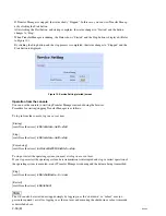
Страница 46: ...ings of the Transfer Manager Number again if you press n key If you press y key the screen changes to the one shown in the Figure 2 and formatting of the local disk is started Figure 2 Formatting the local disk 3 When formatting is completed installation of packages comprising the operating system starts Figure 3 Installation of various packages ...

Страница 47: ...y HP 5 After this copy process is completed the system is automatically restarted Figure 5 First restart n Installation of the drivers made by HP and Transfer Manager is automatically performed at the first restart of the system The screen shown in the Figure 5 remains displayed for about 30 minutes during installation If the screen disappears in the course of installation press the Shift key to r...

Страница 48: ...ler zzz NetIF build number that is included in the Installer 2 Login prompt and the startup message of Transfer Manager TM MediaVenue1 login Shows the login prompt TM MediaVenue1 is a host name that has been set Starting Waiting for FM Shows the startup message of Transfer Manager You can check whether Transfer Manager has started up or not by confirming these messages If they are displayed you ca...

Страница 49: ... with File Manager If you want to start stop Transfer Manager in the desired timing you can use the browser or console to do so Operation from the browser To operate from the browser enter http the IP address of the Transfer Manager Global Network in the address field of the browser Figure 8 Top screen If you enter http the IP address of the Transfer Manager Global Network the top screen as shown ...

Страница 50: ...r starting stopping Transfer Manager is as follows To log in from the console log in as a root user Startup root localhost root sbin service netif start Stop root localhost root sbin service netif stop Forced stop root localhost root usr local netif bin netif sh stop To stop or restart the operating system you must also log in as a root user If you stop or restart the operating system data transmi...

Страница 51: ...he operation procedures refer to the manual supplied with McDATA FC Switch 2 6 1 Preparation Setting the IP Address 1 Connect FC Switch and the PC with a serial cable 2 Launch the terminal software such as Hyper Terminal 3 Configure the communication parameters of the terminal software Baud rate 115200 Data bit 8 Parity None Stop bit 1 Flow control Hardware 4 Configure the IP address as follows xx...

Страница 52: ...fault Zone 4 Operations Switch Online State Set Online Set 1 back to the original value 5 Configure Ports Type Gx Port Fx Port n Configure all ports that you use 6 Configure Ports Type Speed Negotiate Default n Configure all ports that you use ...

Страница 53: ... Corporation Sony Corporation interdit formellement la copie de quelque partie que ce soit de ce manuel ou son emploi pour tout autre but que des opérations ou entretiens de l équipement à moins d une permission écrite de Sony Corporation Das in dieser Anleitung enthaltene Material besteht aus Informationen die Eigentum der Sony Corporation sind Die Sony Corporation untersagt ausdrücklich die Verv...

Страница 54: ...Printed in Japan Sony Corporation 2006 8 16 2005 NSS V2 SY BKNS V202 SY BKNS V203 SY BKNS V209 SY J E 3 903 856 02 ...

Отзывы: