


41
Others
Others
I/O Port
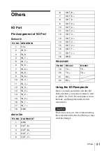
Pin Assignment of I/O Port
Sensor In
Alarm Out
RS-422/485
Using the I/O Receptacle
Insert a slotted screwdriver into the slot
above the hole you want to connect a wire
to (AWG No. 26 to 20), insert the wire in
the hole, and then pull out the slotted
screwdriver.
Do not use excessive force when inserting
the screwdriver into the slot. Doing so may
result in damage.
Pin NO. SENSOR IN
1
3.3 v
2
IN_8 –
3
IN_8
4
IN_7 –
5
IN_7 +
6
IN_6 –
7
IN_6 +
8
IN_5 –
9
IN_5 +
10
IN_4 –
11
IN_4 +
12
IN_3 –
13
IN_3 +
14
IN_2 –
15
IN_2 +
16
IN_1 –
17
IN_1 +
18
GND
Pin NO. ALARM OUT
1
GND
2
OUT_8 –
3
OUT_8 +
4
OUT_7 –
5
OUT_7 +
6
OUT_6 –
7
OUT_6 +
8
OUT_5 –
9
OUT_5 +
10
OUT_4 –
11
OUT_4 +
12
OUT_3 –
13
OUT_3 +
14
OUT_2 –
15
OUT_2 +
16
OUT_1 –
17
OUT_1 +
18
GND
Pin NO. RS-422
RS-485
19
TX –
TX –
20
TX +
TX +
21
RX –
22
RX +
Caution
Содержание NSR-500
Страница 274: ...274 Especificaciones ...
Страница 275: ...275 Especificaciones ...
Страница 276: ...Sony Corporation 1 7 1 Konan Minato ku Tokyo 108 0075 Japan Printed in Taiwan ...