


23
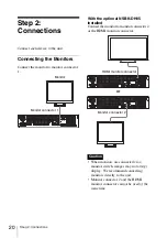
Step 2: Connections
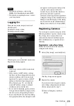
For RS-422 (VISCA, PELCO-D)
communication
Configure a daisy chain connection as
follows.
Maximum number of cameras: 7
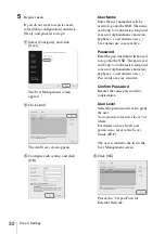
For RS-485 (PELCO-D)
communication
Configure a star connection as follows.
Maximum number of cameras: 16
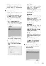
When using cameras and power supply units
that superimpose DC voltage on the video
coaxial cable, pay close attention to the coaxial
cable wiring. If the camera cable on which DC
voltage is superimposed is connected to the
NSR, malfunctions may occur.
• To perform pan, tilt, and zoom, control
numbers must be configured. Be sure that
the numbers do not overlap when
multiple analog cameras are connected.
For details on configuring control
numbers, refer to the operating
instructions for the analog camera.
• For details on the pin assignment for the
Assignment of I/O Port” (page 41)
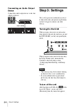
Connecting Other Devices
Connecting Sensor Inputs
and Alarm Outputs
Connect the wires to the sensor input
connector and the alarm output connector.
For details, see
Connecting an
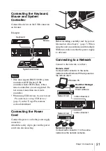
Uninterruptible Power Supply
(UPS)
1
Connect the UPS to the power outlet.
2
Connect the NSR to the UPS with the
power cord.
3
Connect the NSR to the UPS with the
dedicated serial cable to the
RS-232C 1 (UPS) connector on the
rear of the NSR.
Caution
4
To RS-422
connector
Analog
camera
PTZ
4
To RS-485
connector
Analog
camera
PTZ
Analog
cameras
Power
supply
unit
VIDEO
OUT
NSR
Coaxial cable
Coaxial cable
on which DC
voltage is
superimposed
Be careful not to connect
the coaxial cable for the
analog cameras to the
NSR unit.
Notes
Power cord
To Power source
UPS
Serial cable
Содержание NSR-500
Страница 274: ...274 Especificaciones ...
Страница 275: ...275 Especificaciones ...
Страница 276: ...Sony Corporation 1 7 1 Konan Minato ku Tokyo 108 0075 Japan Printed in Taiwan ...