1-42
MVS-8000X/7000X
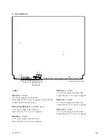
D500 (L-1) :
+
1.0 V
+
1.0 V power supply status indication.
Lights when the
+
1.0 V power is supplied.
D3603 (G-1) : PLL UNLOCK
Indicates lock/unlock of the PLL (Phase Locked Loop) in
the FPGA.
If this LED lit, the PLL can possibly be unlocked.
D3604 (G-1) : CONF ERR
Indicates the con
fi
guration error of the FPGA.
If this LED lit, the FPGA can possibly be working incor-
rectly.
D4000 (F-1) : INET LINK
Lights when linked Ethernet 1 on CPU module with the
CA board.
D4001 (F-1) : INET ACT
Blinks when linking Ethernet 1 on the CPU module with
the CA board and receiving/transmitting the data.
D4002 (G-1) : EXT LINK/ACT
Lights when the FM DATA LAN linked, and blinks when
communicating.
D3605 to D3620 (N-1) : CPU STATUS
Indicates CPU status on board.
D3500 (G-1) : CC_UNLOCK
Indicates lock/unlock of the clock conditioner.
If this LED lit, the clock conditioner can possibly be
unlocked.
< Switch >
S3100 (J-1) : RST
This is reset switch for the MY board.
Pressing this switch initializes the CPU on the MY board.
S3001 (J-1) : MON
The switch that is used to reset the monitor during mainte-
nance through the terminal.
< LED on the CPU-DP Module >
Refer to < LED on the CPU-DP Module > in “1. CA-82
board”.
< Switch on the CPU-DP Module >
Refer to < Switch on the CPU-DP Module > in “1. CA-82
board”.
Содержание MVS-8000X System
Страница 4: ......
Страница 54: ......
Страница 58: ...Sony Corporation MVS 7000X SY MVS 8000X SY E 4 189 509 03 Printed in Japan 2011 5 08 2010 ...


