1-35
MVS-8000X/7000X
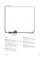
6. XPT-31, XPT-31A Boards
R
P
N
M
L
K
J
H
G
E
D
C
B
A
1
2
3
4
5
6
7
8
9
10
11
12
F
D203
D403
D401
D1101
D1
104
D1
103
D1
102
D
111
2
D1301
D1302
D1302
D1301
D1
11
1
D1
108
D1
109 D
111
4
D1113
D1110
D1107
D1
120
D1
119
D
111
6
D
111
7
D1
122
D1121
D1118
D1115
S501
S1102
S701
CPU-DP
Module
6
5
4
3
2
1
A
B
C
D
E
F
G
H
D1
D3
D5
D2
D4
D16
D17
D11
D10
D9
D8
D7
D15
D14
D13
D12
D6
SW2
Side A (Component Side)
< LED >
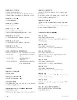
D203 (D-1) : 12 V
+
12 V power supply status indication.
Lights when the
+
12 V power is supplied. If this LED does
not light, the fuse may have blown.
D401 (D-1) : 1.2 V-2
+
1.2 V-2 power supply status indication.
Lights when the
+
1.2 V power is supplied.
D403 (D-1) : 3.3 V
+
3.3 V power supply status indication.
Lights when the
+
3.3 V power is supplied.
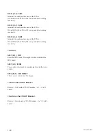
D1101 (E-1) : CONF ERR
Indicates the con
fi
guration error of the IC601.
If this LED lit, the IC601 can possibly be working incor-
rectly.
D1102 (C-1) : STATUS
For future expansion.
D1103 (C-1) : BECON
For future expansion.
D1104 (B-1) : POWER
Power supply status indication.
Lights in green when all power supply on the board are
normally. If the power supply has abnormality, turns off.
Содержание MVS-8000X System
Страница 4: ......
Страница 54: ......
Страница 58: ...Sony Corporation MVS 7000X SY MVS 8000X SY E 4 189 509 03 Printed in Japan 2011 5 08 2010 ...


