— 97 —
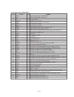
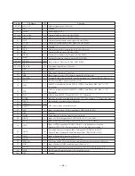
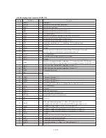
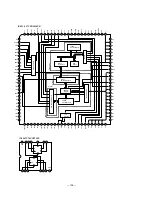
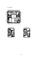
• IC407 Shock-Proof Memory Controller, ATRAC Encoder/Decoder (CXD2536CR)
Pin No.
Pin Name
I/O
Function
1
2
3
4
5
6
7
8
9
10
11
12
13
14
15
16
17
18 to 21
22
23
24
25
26
27
28
29
30
31
32
33
34
35
36
37
38
39
40
41
42
43
44
45 to 47
VDD
SWDT
SCK
XLAT
SRDT
SENSE
SCMD0
SCMD1
XINT
RCPB
WRMN
TX
VSS
SICK
IDSL
XILT
XRST
TS0 to TS3
EXIR
SASL
SNGLE
VSS
AIRCPB
XRQ
ADTO
ADTI
XALT
ACK
AC2
LCHST
EXE
MUTE
OSCO
OSCI
VSS
ATT
F86
DOUT
ADIN
ABCK
ALRCK
SA2 to SA0
—
I
I
I
O/Z
O/Z
I
I
O
I
I
I
—
I
I
I
I
I
I
I
I
—
O
I/O
I/O
I/O
I/O
I/O
I/O
I/O
I/O
I/O
O
I
—
I/O
O
O
I
O
O
O
Power supply (+5V)
Input of write data signal from system controller (IC301)
Input of serial clock signal from system controller (IC301)
Input of serial latch signal from system controller (IC301)
Output of read data signal to system controller (IC301)
Output of internal status (SENSE) to system controller (IC301) (Not used)
Input of serial command control mode (Fixed at “H”)
Output of interrupt status to system controller (IC301)
Recording/playback switching input (Fixed at “L”)
Input of write/monitor mode switching signal (Fixed at “L”)
Input of write data transmission timing from system controller (IC301)
Also used as magnetic field head ON/OFF output
Ground
Chip reservation (Fixed at “L”)
Chip reservation (Fixed at “H”)
Input of reset signal from Q403. Reset: “L”
Test pin (Fixed at “L”)
Chip reservation (Fixed at “L”)
Block selection in single use. “L”: ATRAC. “H”: RAM controller (Fixed at “H”)
Normally fixed at “L. Fixed at “H” when used as ATRAC or RAM controller for single
(Fixed at “H”)
Ground
Output of ATRAC and external audio block recording/playback mode signal
ATRAC I/F XRQ signal input/output
ATRAC decode data signal input/output
ATRAC encode data signal input/output
ATRAC I/F XALT signal input/output
ATRAC I/F ACK signal input/output
ATRAC I/F error data signal input/output (Not used)
ATRAC I/F Lch start data signal input/output (Not used)
ATRAC I/F EXE signal input/output (Not used)
ATRAC I/F MUTE signal input/output (Not used)
Clock output (49.152 MHz) (Not used)
Clock input (49.152 MHz) (Not used)
Ground
ATRAC I/F ATT signal input/output (Not used)
ATRAC block 11.6 msec timing signal output (Not used)
Output of monitor/decode audio data signal (Not used)
Input of recording signal (Not used)
Output of bit clock signal (Not used)
Output of L/R clock to A/D and D/A converters (Not used)
Содержание MDS-B5
Страница 2: ... 2 ...
Страница 5: ... 5 SECTION 1 GENERAL This section is extracted from instruction manual ...
Страница 6: ... 6 ...
Страница 7: ... 7 ...
Страница 8: ... 8 ...
Страница 9: ... 9 ...
Страница 10: ... 10 ...
Страница 11: ... 11 ...
Страница 12: ... 12 ...
Страница 13: ... 13 ...
Страница 14: ... 14 ...
Страница 15: ... 15 ...
Страница 16: ... 16 ...
Страница 17: ... 17 ...
Страница 18: ... 18 ...
Страница 19: ... 19 ...
Страница 20: ... 20 ...
Страница 21: ... 21 ...
Страница 22: ... 22 ...
Страница 23: ... 23 ...
Страница 24: ... 24 ...
Страница 25: ... 25 ...
Страница 26: ... 26 ...
Страница 27: ... 27 ...
Страница 28: ... 28 ...
Страница 29: ... 29 ...
Страница 30: ... 30 ...
Страница 31: ... 31 ...
Страница 32: ... 32 ...
Страница 49: ......
Страница 50: ......
Страница 51: ......
Страница 52: ......
Страница 53: ......
Страница 54: ......
Страница 55: ......
Страница 56: ......
Страница 57: ......
Страница 58: ......


