background image

— 27 —

KV-27S40 / 27S45 / 27S65 / 29SL40 / 29SL40A / 29SL40C/

29SL45 / 29SL65 / 29SL65C/ 29XL40M / 29XL40P / 29XT11A

A

 BOARD

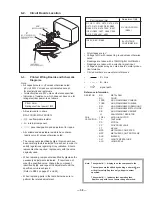
The following adjustments should always be performed when

replacing the following components which are marked with 

]

 on

the schematic diagram:

DY, C511,C572, C573, C574, C575, D573, D574, R582, R583
R585, R586, R578, R579, T504, IC301, IC521, IC603, C507,
C508, C509, C515, C520, L591,L501

(1)

Preparation before Confirmation

Using Variac, apply AC input voltage: 120+2VAC
(or 220 + 2 VAC for KV-29SL40A/29SL40C
29SL65C/29XT11A  ONLY)

1)

Turn the POWER switch ON.

2)

Input a white signal and set the PICTURE and BRIGHT
controls to maximum.

3)

Confirm that the voltage between C574 (+) or TP503 and
ground is more than: 105VDC.

(2)

Hold-down Operation Confirmation

1)

Connect the current meter between Pin 11 of the FBT
(T504) and the PCB land where Pin 

11

 would normally

attach. (see figure 1.0 on next page)

2)

Input a dot signal and set PICTURE and BRIGHTNESS to
minimum: IABL = 100+100

µ

A

3)

Confirm the voltage of A board TP-600 is 135 

±

 3VDC

4)

Connect the Digital Voltmeter and the DC power supply
via diode 1SS119 to C574 (+).  (See figure 1.0 on next
page.)

5)

Increase the DC power voltage gradually until the picture blanks out.

6)

Turn DC power source off immediately.

7)

Read the digital voltmeter indication.

STANDARD
Less than or equal to:

141.3 VDC

8)

Input a white signal and set PICTURE and BRIGHTNESS
to maximum:   

IABL = 1750+100

µ

A

9)

Repeat steps from (4) to (7).

STANDARD
Less than or equal to:

141.3 VDC

SECTION 4

SAFETY RELATED ADJUSTMENTS

The following adjustments should always be performed

           when replacing the following components which are marked

           with 

]

 on the schematic diagram:

IC603, IC601, R699

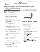
1)

Using Variac, apply AC input voltage: 130 + 2.0 VAC
(or 220.0 

±

 2.0 VAC for KV-29SL40A/29SL40C/

29SL65C/29XT11A only).

2)

Input a dot signal.

3)

Set the PICTURE control and the BRIGHT control to

minimum.

4)

Set to service adjustment mode.

5)

Select PADJ with 

 and 

 .

6)

Adjust with   to the 0 level.

7)

Confirm the voltage of A BOARD TP-600 is less than

138 VDC.

8)

If step 7 is not satisfied, replace the components, repeat the

above steps.

9)

Adjust with   and 

 for:

135 

±

 3 VDC

10) Write into the memory by pressing 

 then

.


B+ VOLTAGE CONFIRMATION AND ADJUSTMENT

(3)

Hold-down Readjustment

If the current setting indicated in step 2-2 cannot be met,

readjustment should be performed by altering the resistance value

of R584, a component marked with 

.

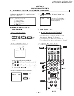
+

I  ABL

ABL

T504

FBT

range

-

ammeter

3.0 mA DC

A

 R584 CONFIRMATION METHOD 


(HV HOLD-DOWN CONFIRMATION)  AND READJUSTMENTS

4. ba4 (2) safety adjustment

6/6/98, 4:31 PM

27

Содержание KV-27S45 Trinitron

Страница 1: ...S65 RM Y167 US SCC S01K A KV 27S65 RM Y167 CND SCC S03G A KV 29SL40 RM Y165 E SCC S04X A KV 29SL40A RM Y165 E SCC S04S A KV 29SL40C RM Y165 E SCC S04U A KV 29SL45 RM Y167 E SCC S04Y A KV 29SL65 RM Y167 E SCC S06F A KV 29SL65C RM Y167 E SCC S04V A KV 29XL40M RM Y165 MX SCC S02D A KV 29XL40P RM Y165 E SCC S04R A KV 29XT11A RM Y165 E SCC S04T A MODEL COMMANDER DEST CHASSIS NO KV 27S45 SERVICE MANUAL ...

Страница 2: ...to change without notice l SRS SOUND RETRIEVAL SYSTEM The l SRS SOUND RETRIEVAL SYSTEM is manu factured by Sony Corporation under license from SRS Labs Inc It is covered by U S Patent No 4 748 669 Other U S and foreign patents pending The word SRS and the SRS symbol l are registered trademarks of SRS Labs Inc BBE and BBE symbol are trademarks of BBE Sound Inc and are licensed by BBE Sound Inc unde...

Страница 3: ...justments 26 4 SAFETY RELATED ADJUSTMENTS 27 5 CIRCUIT ADJUSTMENTS 5 1 Electrical Adjustment by Remote Commander 29 5 2 A Board Adjustments 32 TABLE OF CONTENTS Section Title Page Section Title Page 6 DIAGRAMS 6 1 Block Diagrams 35 6 2 Circuit Boards Location 38 6 3 Printed Wiring Boards and Schematic Diagrams 38 A Board 39 P Board 47 K Board 49 C Board 50 E Board 51 HZ Board 52 6 4 Semiconductors...

Страница 4: ... LORSQU UN MAUVAIS FONTIONNEMENT SUSPECTE WARNINGS AND CAUTIONS SELF DIAGNOSTIC FUNCTION The units in this manual contain a self diagnostic function If an error occurs the STANDBY TIMER lamp will automatically begin to flash The number of times the lamp flashes translates to a probable source of the problem A definition of the STANDBY TIMER lamp flash indicators is listed in the instruction manual...

Страница 5: ...r ON Note that this differs from entering the service mode sound volume Self Diagnostic screen display 5 HANDLING OF SELF DIAGNOSTIC SCREEN DISPLAY Since the diagnostic results displayed on the screen are not automatically cleared always check the self diagnostic screen during repairs When you have completed the repairs clear the result display to 0 Unless the result display is cleared to 0 the se...

Страница 6: ...f Vertical deflection stopped Occurs when an absence of the vertical deflection pulse is detected by pin 17 of IC001 Power supply will shut down when waveform interval exceeds 2 seconds White balance failure If the RGB levels do not balance within 2 seconds after the power is turned on this error will be detected by IC301 TV will stay on but there will be no picture Refers to the RGB levels of the...

Страница 7: ...hardware have been replaced Be absolutely certain that you have replaced all the insulators 4 Look for unauthorized replacement parts particularly transistors that were installed during a previous repair Point them out to the customer and recommend their replacement 5 Look for parts which though functioning show obvious signs of deterioration Point them out to the customer and recommend their repl...

Страница 8: ... twin lead cable Rear of TV VHF UHF 75 ohm coaxial cable 75 ohm coaxial cable 300 ohm twin lead cable Rear of TV VHF UHF EAC 66 U V mixer not supplied No connection TO CONVERTER in this case CATV cable Antenna cable Connecting directly to cable or an antenna Cable and antenna Note In order to receive channels with an antenna you will need to turn your CABLE to OFF see page 23 and perform the AUTO ...

Страница 9: ...27V45 only VCR Connections AUDIO OUT VAR FIX VIDEO IN 1 2 VHF UHF S VIDEO VIDEO L R AUDIO MONO AUDIO R AUDIO L VIDEO S VIDEO LINE OUT OUT IN Coaxial cable Rear of TV VMC 810S 820S not supplied Cable VCR 3 1 2 AUDIO R red AUDIO L white VIDEO yellow AUDIO OUT VAR FIX VIDEO IN 1 2 VHF UHF SVIDEO VIDEO L R AUDIO MONO AUDIO R AUDIO L VIDEO S VIDEO LINE OUT OUT IN OUT IN VMC 810S 820S not supplied Cable...

Страница 10: ...SVIDEO VIDEO L R AUDIO MONO AUDIO R AUDIO L VIDEO AUDIO R AUDIO L VIDEO SATELLITE IN VHF UHF S VIDEO OUT IN LINE OUT LINE IN VHF UHF S VIDEO OUT IN LINE OUT AUDIO R red AUDIO L white VIDEO yellow 1 2 3 VMC 810S 820S not supplied VMC 810S 820S not supplied 4 5 Rear of TV DBS receiver VCR Connecting a DBS Direct Broadcast Satellite receiver and a VCR Note To view from the DBS or VCR select the video...

Страница 11: ...an S Video equipped camcorder you can use an S Video connection for optimum picture quality IN VIDEO 1 VHF UHF L R AUDIO MONO VIDEO 3 MONITOR AUDIO VAR FIX OUT TO CONVERTER AUX S VIDEO VIDEO LINE OUT OUT IN LINE IN OUT IN AUDIO R AUDIO L VIDEO AUDIO R AUDIO L VIDEO Disconnect all power sources before making any connections Connecting two VCRs for tape editing using MONITOR OUT VCR for playback VCR...

Страница 12: ...are stored the lowest numbered channel is displayed If the TV receives cable TV channels CABLE is set ON automatically To perform AUTO SET UP again Press SET UP on the TV Press CH or CH to select a language Press VOL to restore factory settings CONTINUE TO AUTO PROGRAM will appear on the screen Press CH to continue or CH to exit Press SET UP to exit Note When you perform AUTO PROGRAM your CHANNEL ...

Страница 13: ... length and time of the show if the broadcaster offers this service Note Poor reception of TV programs can cause errors in CAPTION VISION and XDS Captions may appear with a white box or other errors instead of intended text CAPTION VISION SET UP CHANNEL SET UPŁ FAVORITE CHANNELŁ CHANNEL BLOCKŁ VIDEO LABELŁ CAPTION VISION CC1 MENU Move Select Exit MENU Press to freeze the window picture while in PI...

Страница 14: ...deo inputs TV VIDEO 1 VIDEO 2 and VIDEO 3 KV 27S45 27S65 27V45 27V65 only If you have a single tuner your PIP input source is the VCR Press to alternate sound between the main picture and the window picture A will appear for a few seconds to indicate which picture is receiving sound Using your New TV continued 17 Press to change the TV channel in the window picture KV 27S65 27V65 only For models K...

Страница 15: ...Ł AUTO PROGRAM CHANNEL SKIP ADDŁ CHANNEL CAPTIONŁ MENU Move Select Exit MENU SET UP CHANNEL SET UPŁ FAVORITE CHANNELŁ CHANNEL BLOCKŁ VIDEO LABELŁ CAPTION VISION CC1Ł LANGUAGE ENGLISH MENU Move Select Exit MENU CHANNEL SET UPŁ Ł CABLE ONŁ CHANNEL FIX OFFŁ AUTO PROGRAM CHANNEL SKIP ADDŁ CHANNEL CAPTIONŁ MENU Move Select Exit MENU Using your Menus 19 MODE Customized picture viewing PICTURE Picture Ad...

Страница 16: ... TV s sound only through external audio system speakers AUDIO OUT can only be set when speakers are set to OFF VARIABLE Sound output varies according to the TV settings Useful when you want to use your remote control to control the output of a separate audio system FIXED Sound output is held at a fixed level through your stereo Using your Menus continued 21 OPTIONS Enhanced audio options With the ...

Страница 17: ...s for viewing With the CHANNEL SET UP menu open 1 Use V or v to access the feature you want to change 2 Press to select the feature CABLE Select ON if your TV is connected to a cable system After setting CABLE you will need to run AUTO PROGRAM CHANNEL FIX Press and then use the V or v buttons to set the TV s input to one of the following options 2 6 When a cable box is connected to the VHF UHF inp...

Страница 18: ...t MENU 25 FAVORITE CHANNEL Quick access to favorite channels VIDEO LABEL Easy recognition of connected equipment e g DBS VHS etc LANGUAGE Setting FAVORITE CHANNEL 1 Press and then V or v to select AUTO or MANUAL Selecting AUTO will display the last five channels chosen with the remote control 2 Press V or v to move the cursor to 1 2 3 4 or 5 and press 3 Press V or v to access the desired channel a...

Страница 19: ...s Press or 0 during playback To resume normal playback release the button Press TV VTR 1 Press CODE SET 2 Press VTR DVD FUNCTION 3 Use the 0 9 buttons to key in the manufacturer s code number from the following chart 4 Press ENTER VCR manufacturer code numbers Manufacturer Code Sony 301 302 303 Aiwa 338 344 Broksonic 319 317 Canon 309 308 Daewoo 341 312 309 Emerson 319 320 316 317 318 341 Fisher 3...

Страница 20: ...a Code 801 preset code for remote control 802 805 804 803 802 808 806 807 Operating a cable box or DBS receiver 29 Problem What it could be What you can do Troubleshooting Consult the table below it suggests solutions to specific problems If you need more information consult the operating instructions guide Cannot Operate Single Tuner PIP KV 27S45 27V45 A red light keeps flashing on the TV for mor...

Страница 21: ...e page 24 Ensure that CABLE is set to ON in the SET UP menu see page 23 Use AUTO PROGRAM to add receivable channels that are not presently in TV memory see page 24 Press TV FUNCTION and adjust the TV s volume Check your CHANNEL FIX settings see page 23 CABLE setting may not be set correctly in the SET UP menu Antenna cable connections may not be correct TV may be set to AUX mode CABLE setting may ...

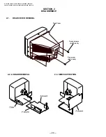
Страница 22: ...5 27S65 29SL40 29SL40A 29SL40C 29SL45 29SL65 29SL65C 29XL40M 29XL40P 29XT11A 2 2 A BOARD REMOVAL 2 3 SERVICE POSITION SECTION 2 DISASSEMBLY 2 1 REAR COVER REMOVAL Rear Cover Seven screws BVTP 4X16 One screw BVTP 3X12 P ...

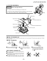
Страница 23: ...ap can be removed by turning the rub ber cap and pulling it in the direction of arrow Use your thumb to pull the rubber cap firmly in the direction indicated by arrow REMOVAL OF THE ANODE CAP NOTE Short circuit the anode of the picture tube and the anode cap to the metal chassis CRT shield or carbon painted on the CRT after removing the anode REMOVAL PROCEDURES WARNING Before removing anode cap H ...

Страница 24: ...rity control to the center as shown in Fig 2 3 Turn the raster signal of the pattern generator to green 4 Move the deflection yoke backward and adjust with the purity control so that green is in the center and red and blue are at the sides evenly Fig 3 5 Move the deflection yoke forward and adjust so that the entire screen becomes green Fig 1 6 Switch over the raster signal to red and blue and con...

Страница 25: ...ce Adjustment Preparation Before starting perform Horizontal and Vertical Static Convergence Adjustment 1 Slightly loosen deflection yoke screw 2 Remove deflection yoke spacers 3 Move the deflection yoke for best convergence as shown below Fig 8 4 Tighten the deflection yoke screw 5 Install the deflection yoke spacers Fig 7 Fig 8 If the blue dot does not converge with red and green dots perform th...

Страница 26: ...illoscope as shown in Fig 11 so that voltages on the red green and blue cathodes are 170Vdc 4 Observe the screen and adjust SCREEN G2 VR to obtain the faintly visible background of dot signal Affix a permalloy assembly corresponding to the misconverged areas Fig 10 7 Turn set off and on to exit 3 6 WHITE BALANCE ADJUSTMENTS 1 Input an entire white signal 2 Set to Service adjustment Mode 3 Set DCOL...

Страница 27: ...tagegraduallyuntilthepictureblanksout 6 Turn DC power source off immediately 7 Read the digital voltmeter indication STANDARD Less than or equal to 141 3 VDC 8 Input a white signal and set PICTURE and BRIGHTNESS to maximum IABL 1750 100µA 9 Repeat steps from 4 to 7 STANDARD Less than or equal to 141 3 VDC SECTION 4 SAFETY RELATED ADJUSTMENTS The following adjustments should always be performed whe...

Страница 28: ... 28 KV 27V40 27V45 27V65 29VL40 29VL65A 29VL65C 29VL85 29VL95 DIGITAL MULTIMETER TP600 POWER SUPPLY C574 DIGITAL MULTIMETER 1SS119 R582 ABL 11 AMMETER 3mA dc range T504 FBT A BOARD Figure 1 0 24 ...

Страница 29: ...of Setting the Service Adjustment Mode SERVICE MODE PROCEDURE 1 Standby mode Power off 2 on the Remote Commander Press each button within a second SERVICE ADJUSTMENT MODE IN 3 The CRT displays the item being adjusted 4 Press or on the Remote Commander to select the item 5 Press or on the Remote Commander to change the data 6 Press then to write into memory SERVICE ADJUSTMENT MODE MEMORY Green SERV...

Страница 30: ... LIN ADJUST 0 15 0 0 24 RDRV R OUTPUT DRIVE CONTROL 0 63 35 40 25 GDRV G OUTPUT DRIVE CONTROL 0 63 30 35 26 BDRV B OUTPUT DRIVE CONTROL 0 63 30 35 27 RCUT R OUTPUT CUTOFF CONTROL 0 15 10 7 28 GCUT G OUTPUT CUTOFF CONTROL 0 15 7 5 29 BCUT B OUTPUT CUTOFF CONTROL 0 15 7 5 30 DCOL DYNAMIC COLOR ON OFF 0 1 0 1 31 SHUE SUB HUE 0 31 14 8 32 SCOL SUB COLOR 0 31 14 14 14 14 33 SBRT SUB BRIGHTNESS 0 31 11 ...

Страница 31: ...DR Y2 DRIVE 0 31 20 20 77 U2DR U2 DRIVE 0 31 18 18 78 V2DRV V2 DRIVE 0 31 9 9 79 PSFO PIP SHP F0 0 1 1 1 80 PCD2 PIP CD MODE 2 0 1 1 1 1 81 PDCT PIP DC TRAN 0 7 4 4 82 PP O PIP PRE OVER 0 3 1 1 83 PDLY PIP Y DELAY 0 3 0 0 84 PBG PIP BG 0 15 5 5 85 PEXT PIP EXT COLOR 0 1 1 0 1 0 86 PHMK 0 1 0 0 87 ABL0 0 1 0 0 88 ABL1 0 7 1 1 89 PHPO PIP HORIZONTAL POSITION 0 63 58 58 90 PVPO PiP VERTICAL POSiTiON ...

Страница 32: ...tions with standard setting 3 Connect the frequency counter across TP 508 or CN501 VDY pin 6 connector and ground 4 Check V Frequency for the 60 2 Hz NTSC 5 Check V Frequency for the 50 2 Hz Trinorma SUB CONTRACT ADJUSTMENT SCON 1 Input a color bar signal 2 Select the red color 3 Set to Service adjustment Mode 4 Select the item DCOL to 0 level 5 Set the conditions as follows PICTURE MAX COLOR MIN ...

Страница 33: ...n SUB BRIGHT ADJUSTMENT SBRT 1 Input a cross hatch signal 2 Set to Service adjustment Mode 3 Set the PICTURE and BRIGHT to minimum 4 Select SBRT with and 5 Adjust with and to obtain a faintly visible cross hatch 6 Write into the memory by pressing then SUB HUE SUB COLOR ADJUSTMENT SHUE SCOL 1 Input a color bar signal 2 Set to Service adjustment Mode 3 Select the item DCOL and set to 0 level 4 Conn...

Страница 34: ...eristic curve B unless otherwise noted The components identified by in this manual have been carefully factory selected for each set in order to satisfy regulations regarding X ray radiation Should replacement be required replace only with the value originally used When replacing components identified by make the necessary adjustments indicated If results do not meet the specified value change the...

Страница 35: ......

Страница 36: ......

Страница 37: ......

Страница 38: ......

Страница 39: ......

Страница 40: ......

Страница 41: ......

Страница 42: ...G 1SS133T 77 ERC06 15S MDV04 600 S2L60F EZ0150AV1 2SA1175 HFE 2SC2785 HFE 2SA933AS QRT 2SC3209LK 2SD1312 K 2SD774 34 2SC4159 E MX0541B F RD9 1EW MA111 D1NL20 TA EGP20G EL1Z 1SS83 D3SB60F D10SC4M D2S4MF 2SK2845 LB102 2SC5426 01 E B C E LETTER SIDE C B E C B B C E CATHODE ANODE CATHODE ANODE CATHODE ANODE CATHODE ANODE 1 2 3 123 CATHODE ANODE S D G B C E B1 E1 C1 C2 B2 E2 ...

Страница 43: ...CORD POWER KV 29SL40C 17 1 783 838 41 CORD POWER KV 29XT11A 29SL40A 18 1 453 268 11 TRANSFORMER ASSY FLYBACK NX 4005 X4J4 19 4 064 646 01 CLIP CHASSIS 20 1 766 374 11 PLUG F PIN 21 8 598 431 00 TUNER FSS BTF WA411 22 A 1298 484 A A BOARD COMPLETE KV 27S40 29SL40 29XL40M 29XL40P 22 A 1298 543 A A BOARD COMPLETE KV 29XT11A 29SL40A 22 A 1298 542 A A BOARD COMPLETE KV 29SL40C 22 A 1298 483 A A BOARD C...

Страница 44: ...WASHER 7 8 733 873 05 CRT29NX KV 27S65 29SL65 7 8 733 874 05 CRT29 NX KV 29SL65C 9 4 041 268 01 SCREW 7 TAPPING 10 8 451 486 11 DY Y29 NXA V KV 27S65 29SL65 10 8 451 486 21 DY Y29 NXA V2 KV 29SL65C 11 4 053 005 01 SPACER DY 12 A 1331 775 A C BOARD COMPLETE 13 3 704 372 31 HOLDER HV 14 4 036 329 01 SPRING B TENSION 15 1 416 588 11 COIL DEMAGNETIC KV 27S65 29SL65 15 1 416 589 21 COIL DEMAGNETIC KV 2...

Страница 45: ...ay should be anticipated when ordering these items Items with no part number and no description are not stocked because they are seldom required for routine service The components identified with gray shading and a critical symbol are critical for safety Replace only with part number specified Note Les composants identifies per un trame et une marque sont critiques pout la securite Ne les remplace...

Страница 46: ...ed by an asterisk on the A board schematic or by the word variant on the common parts list Model Page KV 27S40 29XL40M 29XL40P 29SL40 68 KV 29SL65C 70 KV 27S45 29SL45 72 KV 27S65 29SL65 74 KV 29SL40C 76 KV 29XT11A 29SL40A 78 C BOARD COMPLETE PARTS LIST All Models 79 E BOARD COMPLETE PARTS LIST All Models 79 K BOARD COMPLETE PARTS LIST KV 29SL65C 27S65 29SL65 only 80 P BOARD COMPLETE PARTS LIST KV ...

Страница 47: ... 964 11 ELECT 10MF 20 50V C081 1 126 964 11 ELECT 10MF 20 50V C091 1 163 231 11 CERAMIC CHIP 15PF 5 50V C092 1 163 231 11 CERAMIC CHIP 15PF 5 50V C101 1 126 963 11 ELECT 4 7MF 20 50V C102 1 126 382 11 ELECT 100MF 20 16V C150 1 126 941 11 ELECT 470MF 20 25V C151 1 104 664 11 ELECT 47MF 20 25V C200 VARIANT SEE VARIANT PARTS LIST C201 1 126 960 11 ELECT 1MF 20 50V C202 1 126 960 11 ELECT 1MF 20 50V C...

Страница 48: ...1 1 164 232 11 CERAMIC CHIP 0 01MF 10 50V C372 1 164 232 11 CERAMIC CHIP 0 01MF 10 50V C373 1 163 038 91 CERAMIC CHIP 0 1MF 25V C374 1 126 935 11 ELECT 470MF 20 16V C375 1 163 038 91 CERAMIC CHIP 0 1MF 25V C376 1 104 664 11 ELECT 47MF 20 25V C377 1 126 964 11 ELECT 10MF 20 50V C380 VARIANT SEE VARIANT PARTS LIST C381 VARIANT SEE VARIANT PARTS LIST C382 VARIANT SEE VARIANT PARTS LIST C390 1 126 959...

Страница 49: ...6 959 11 ELECT 0 47MF 20 50V C691 1 126 941 11 ELECT 470MF 20 25V C692 1 104 664 11 ELECT 47MF 20 25V C693 1 136 173 00 FILM 0 47MF 5 50V FILTER CF001 1 767 487 11 VIBRATOR CRYSTAL CONNECTOR CN101 1 508 786 00 PIN CONNECTOR 5MM PITCH 2P CN150 VARIANT SEE VARIANT PARTS LIST CN203 1 560 124 00 PLUG CONNECTOR 2 5MM 4P CN301 1 564 509 11 PLUG CONNECTOR 6P CN302 VARIANT SEE VARIANT PARTS LIST CN401 1 5...

Страница 50: ...ARIANT SEE VARIANT PARTS LIST IC302 VARIANT SEE VARIANT PARTS LIST IC401 8 759 490 17 IC TDA7057AQ N2 4 382 854 11 SCREW M3X10 P SW for IC401 IC402 8 752 072 39 IC CXA2021S IC521 8 759 700 07 IC NJM2903M IC541 8 759 980 58 IC TDA8172 IC601 8 729 039 65 TRANSISTOR MX0541B F IC603 8 749 012 13 IC DM 58 IC604 8 759 198 03 IC PQ09RF21 JACK J200 1 774 750 21 JACK BLOCK 2P J201 VARIANT SEE VARIANT PARTS...

Страница 51: ...S CHIP 220 5 1 10W R010 1 216 033 00 RES CHIP 220 5 1 10W R011 1 216 033 00 RES CHIP 220 5 1 10W R013 1 216 081 00 RES CHIP 22K 5 1 10W R016 1 216 041 00 RES CHIP 470 5 1 10W R017 1 216 113 00 RES CHIP 470K 5 1 10W R018 1 216 049 91 RES CHIP 1K 5 1 10W R019 1 249 425 11 CARBON 4 7K 5 1 4W R020 1 249 427 11 CARBON 6 8K 5 1 4W R021 1 249 415 11 CARBON 680 5 1 4W R022 1 249 416 11 CARBON 820 5 1 4W R...

Страница 52: ...216 065 91 RES CHIP 4 7K 5 1 10W R242 1 216 083 00 RES CHIP 27K 5 1 10W R243 1 216 689 11 RES CHIP 39K 5 1 10W R244 1 216 049 91 RES CHIP 1K 5 1 10W R245 1 216 049 91 RES CHIP 1K 5 1 10W R246 1 249 425 11 CARBON 4 7K 5 1 4W R247 1 249 425 11 CARBON 4 7K 5 1 4W R248 1 216 049 91 RES CHIP 1K 5 1 10W R249 1 216 025 91 RES CHIP 100 5 1 10W R250 1 216 033 00 RES CHIP 220 5 1 10W R251 1 216 025 91 RES C...

Страница 53: ...ST R374 VARIANT SEE VARIANT PARTS LIST R375 VARIANT SEE VARIANT PARTS LIST R376 VARIANT SEE VARIANT PARTS LIST R377 VARIANT SEE VARIANT PARTS LIST R378 VARIANT SEE VARIANT PARTS LIST R379 VARIANT SEE VARIANT PARTS LIST R380 VARIANT SEE VARIANT PARTS LIST R381 VARIANT SEE VARIANT PARTS LIST R387 1 216 073 00 RES CHIP 10K 5 1 10W R388 1 216 073 00 RES CHIP 10K 5 1 10W R399 1 216 295 91 SHORT R400 1 ...

Страница 54: ... 21 METAL OXIDE 68K 5 1W F R611 1 220 388 21 METAL OXIDE 68K 5 1W F R612 1 216 353 00 METAL OXIDE 2 2 5 1W F R613 1 216 353 00 METAL OXIDE 2 2 5 1W F R618 1 212 857 00 FUSIBLE 10 5 1 4W F R622 1 249 393 11 CARBON 10 5 1 4W R623 1 249 441 11 CARBON 100K 5 1 4W R624 1 249 421 11 CARBON 2 2K 5 1 4W R630 1 249 421 11 CARBON 2 2K 5 1 4W R631 1 249 429 11 CARBON 10K 5 1 4W R641 1 216 389 11 METAL OXIDE ...

Страница 55: ...N REMARK REF NO PART NO DESCRIPTION REMARK COMMON PARTS LISTING A VARISTOR VDR602 1 809 267 41 VARISTOR ERZV10D471 CRYSTAL X300 VARIANT SEE VARIANT PARTS LIST X301 1 567 505 11 OSCILLATOR CRYSTAL X302 VARIANT SEE VARIANT PARTS LIST ...

Страница 56: ...0UH L351 1 412 031 11 INDUCTOR 47UH TRANSISTOR Q350 8 729 216 22 TRANSISTOR 2SA1162 G Q351 8 729 422 27 TRANSISTOR 2SD601A Q Q352 8 729 216 22 TRANSISTOR 2SA1162 G Q353 8 729 216 22 TRANSISTOR 2SA1162 G Q354 8 729 216 22 TRANSISTOR 2SA1162 G Q355 8 729 422 27 TRANSISTOR 2SD601A Q Q356 8 729 216 22 TRANSISTOR 2SA1162 G Q357 8 729 216 22 TRANSISTOR 2SA1162 G Q358 8 729 422 27 TRANSISTOR 2SD601A Q Q3...

Страница 57: ...W R378 1 216 041 00 RES CHIP 470 5 1 10W R379 1 216 049 91 RES CHIP 1K 5 1 10W R380 1 208 790 11 RES CHIP 2 2K 0 50 1 10W R381 1 216 053 00 RES CHIP 1 5K 5 1 10W R601 1 219 513 11 CARBON 4 7M 5 1 2W R602 1 205 998 11 CEMENTED 1 5 10W R603 1 205 998 11 CEMENTED 1 5 10W THERMISTOR THP601 1 809 539 11 THERMISTOR POSITIVE KV 27S40 29XL40M 29XL40P 29SL40 Note The components identified with shading and ...

Страница 58: ...RITE BEAD FB350 1 216 295 91 SHORT IC IC010 8 759 710 85 IC NJM2233BD IC301 8 752 083 09 IC CXA2061S IC302 8 752 385 80 IC CXD2073S JACK J201 1 774 751 11 TERMINAL BLOCK S J202 1 774 749 11 JACK BLOCK 3P COIL L350 1 412 029 11 INDUCTOR 10UH L351 1 412 031 11 INDUCTOR 47UH TRANSISTOR Q350 8 729 216 22 TRANSISTOR 2SA1162 G Q351 8 729 422 27 TRANSISTOR 2SD601A Q Q352 8 729 216 22 TRANSISTOR 2SA1162 G...

Страница 59: ...P 100 5 1 10W R375 1 216 053 00 RES CHIP 1 5K 5 1 10W R376 1 216 049 91 RES CHIP 1K 5 1 10W R377 1 216 049 91 RES CHIP 1K 5 1 10W R378 1 216 041 00 RES CHIP 470 5 1 10W R379 1 216 049 91 RES CHIP 1K 5 1 10W R380 1 208 790 11 RES CHIP 2 2K 0 50 1 10W R381 1 216 053 00 RES CHIP 1 5K 5 1 10W R600 1 247 289 00 CARBON 8 2M 5 1W R602 1 205 997 11 CEMENTED 2 2 5 10W R603 1 205 997 11 CEMENTED 2 2 5 10W T...

Страница 60: ...TOR 10UH L351 1 412 031 11 INDUCTOR 47UH TRANSISTOR Q350 8 729 216 22 TRANSISTOR 2SA1162 G Q351 8 729 422 27 TRANSISTOR 2SD601A Q Q352 8 729 216 22 TRANSISTOR 2SA1162 G Q353 8 729 216 22 TRANSISTOR 2SA1162 G Q354 8 729 216 22 TRANSISTOR 2SA1162 G Q355 8 729 422 27 TRANSISTOR 2SD601A Q Q356 8 729 216 22 TRANSISTOR 2SA1162 G Q357 8 729 216 22 TRANSISTOR 2SA1162 G Q358 8 729 422 27 TRANSISTOR 2SD601A...

Страница 61: ...49 91 RES CHIP 1K 5 1 10W R378 1 216 041 00 RES CHIP 470 5 1 10W R379 1 216 049 91 RES CHIP 1K 5 1 10W R380 1 208 790 11 RES CHIP 2 2K 0 50 1 10W R381 1 216 053 00 RES CHIP 1 5K 5 1 10W R601 1 219 513 11 CARBON 4 7M 5 1 2W R602 1 205 998 11 CEMENTED 1 5 10W R603 1 205 998 11 CEMENTED 1 5 10W THERMISTOR THP601 1 809 539 11 THERMISTOR POSITIVE Note The components identified with shading and a critic...

Страница 62: ... FERRITE BEAD FB350 1 216 295 91 SHORT IC IC010 8 759 710 85 IC NJM2233BD IC301 8 752 083 09 IC CXA2061S IC302 8 752 385 80 IC CXD2073S JACK J201 1 774 751 11 TERMINAL BLOCK S J202 1 774 749 11 JACK BLOCK 3P COIL L350 1 412 029 11 INDUCTOR 10UH L351 1 412 031 11 INDUCTOR 47UH TRANSISTOR Q350 8 729 216 22 TRANSISTOR 2SA1162 G Q351 8 729 422 27 TRANSISTOR 2SD601A Q Q352 8 729 216 22 TRANSISTOR 2SA11...

Страница 63: ...025 91 RES CHIP 100 5 1 10W R375 1 216 053 00 RES CHIP 1 5K 5 1 10W R376 1 216 049 91 RES CHIP 1K 5 1 10W R377 1 216 049 91 RES CHIP 1K 5 1 10W R378 1 216 041 00 RES CHIP 470 5 1 10W R379 1 216 049 91 RES CHIP 1K 5 1 10W R380 1 208 790 11 RES CHIP 2 2K 0 50 1 10W R381 1 216 053 00 RES CHIP 1 5K 5 1 10W R601 1 219 513 11 CARBON 4 7M 5 1 2W R602 1 205 998 11 CEMENTED 1 5 10W R603 1 205 998 11 CEMENT...

Страница 64: ...SISTOR 2SA1162 G Q351 8 729 422 27 TRANSISTOR 2SD601A Q Q352 8 729 216 22 TRANSISTOR 2SA1162 G Q353 8 729 216 22 TRANSISTOR 2SA1162 G Q354 8 729 216 22 TRANSISTOR 2SA1162 G Q355 8 729 422 27 TRANSISTOR 2SD601A Q Q356 8 729 026 49 TRANSISTOR 2SA1037AK T146 R Q357 8 729 216 22 TRANSISTOR 2SA1162 G Q358 8 729 422 27 TRANSISTOR 2SD601A Q Q359 8 729 216 22 TRANSISTOR 2SA1162 G Q360 8 729 216 22 TRANSIS...

Страница 65: ...5 1 10W R380 1 208 790 11 RES CHIP 2 2K 0 50 1 10W R381 1 216 053 00 RES CHIP 1 5K 5 1 10W R602 1 205 997 11 CEMENTED 2 2 5 10W R603 1 205 997 11 CEMENTED 2 2 5 10W THERMISTOR THP601 1 809 827 11 THERMISTOR POSITIVE KV 29SL40C Note The components identified with shading and a critical symbol are critical for safety Replace only with part number specified Note Les composants identifies per un trame...

Страница 66: ...DIODE LNK0120022G1 IC IC301 8 752 082 35 IC CXA2060AS JACK J201 1 774 749 11 JACK BLOCK PIN RESISTOR R064 1 216 295 91 SHORT R081 1 249 413 11 CARBON 470 5 1 4W R300 1 216 295 91 SHORT R302 1 216 295 91 SHORT R307 1 216 051 00 RES CHIP 1 2K 5 1 10W R600 1 247 289 00 CARBON 8 2M 5 1W R602 1 205 997 11 CEMENTED 2 2 5 10W R603 1 205 997 11 CEMENTED 2 2 5 10W THERMISTOR THP601 1 809 827 11 THERMISTOR ...

Страница 67: ...2WF R1763 1 247 807 31 CARBON 100 5 1 4W R1764 1 247 807 31 CARBON 100 5 1 4W R1765 1 247 807 31 CARBON 100 5 1 4W A 1343 525 A E BOARD COMPLETE A 1343 526 A E BOARD COMPLETE CAPACITOR C5000 1 107 652 11 ELECT 10MF 20 250V C5002 1 107 652 11 ELECT 10MF 20 250V C5003 1 136 601 11 FILM 0 01MF 10 630V C5004 1 130 471 00 MYLAR 0 001MF 5 50V C5006 1 130 471 00 MYLAR 0 001MF 5 50V C5007 1 130 467 00 MYL...

Страница 68: ...7 11 PLUG CONNECTOR 4P COIL L1001 1 408 421 00 INDUCTOR 100UH L1002 1 410 470 11 INDUCTOR 10UH TRANSISTOR Q1001 8 729 119 78 TRANSISTOR 2SC2785 HFE Q1002 8 729 026 41 TRANSISTOR 2SA933AS QRT Q1003 8 729 026 41 TRANSISTOR 2SA933AS QRT Q1004 8 729 026 41 TRANSISTOR 2SA933AS QRT Q1005 8 729 026 41 TRANSISTOR 2SA933AS QRT RESISTOR R1001 1 247 807 31 CARBON 100 5 1 4W R1002 1 247 807 31 CARBON 100 5 1 ...

Страница 69: ...1 11 CERAMIC CHIP 15PF 5 50V C3365 1 163 133 00 CERAMIC CHIP 470PF 5 50V C3366 1 164 005 11 CERAMIC CHIP 0 47MF 25V C3367 1 126 963 11 ELECT 4 7MF 20 50V C3368 1 164 005 11 CERAMIC CHIP 0 47MF 25V C3369 1 163 251 11 CERAMIC CHIP 100PF 5 50V C3370 1 164 346 11 CERAMIC CHIP 1MF 16V C3371 1 163 017 00 CERAMIC CHIP 0 0047MF 10 50V C3372 1 164 005 11 CERAMIC CHIP 0 47MF 25V CONNECTOR CN3301 1 691 632 1...

Страница 70: ... 5 1 10W R3364 1 216 043 91 RES CHIP 560 5 1 10W R3369 1 216 053 00 RES CHIP 1 5K 5 1 10W R3370 1 216 053 00 RES CHIP 1 5K 5 1 10W R3371 1 216 033 00 RES CHIP 220 5 1 10W R3375 1 216 037 00 RES CHIP 330 5 1 10W R3376 1 216 071 00 RES CHIP 8 2K 5 1 10W R3377 1 216 073 00 RES CHIP 10K 5 1 10W R3378 1 216 053 00 RES CHIP 1 5K 5 1 10W R3379 1 216 077 00 RES CHIP 15K 5 1 10W R3380 1 216 025 91 RES CHIP...

Страница 71: ...s only REF NO PART NO DESCRIPTION REMARK REF NO PART NO DESCRIPTION REMARK BOARD VARIANT PARTS LIST A 84 Sony Corporation Sony Technology Center Product Quality Division Service Promotion Department 9 965 841 01 English 98DJ74425 1 Printed in U S A 1998 4 ...

Отзывы: