background image

Installing and Connecting the Projection TV

17

In

sta

lling

 and

 Conne

ctin

g the

 Pr
oj

ecti

on TV

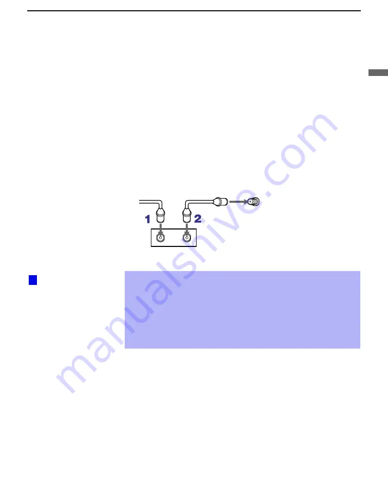
Cable Box Only

Use this hookup if:

You subscribe to a cable TV system that uses scrambled or encoded 
signals requiring a cable box to view all channels, and

You do not intend to hook up any other audio or video equipment to 
your projection TV.

When all channels are routed through your cable box, only one unscrambled 
channel is sent to the projection TV, so you cannot use the Twin View 
feature. If some channels are scrambled, but others are not, consider using 
the hookup on page 16 instead.

1

Connect the coaxial connector from your cable service to the cable 
box’s IN jack.

2

Using a coaxial cable, connect the cable box’s OUT jack to the TV’s 
VHF/UHF jack.

Also, set Cable to ON in the Channel menu. (see page 49)

If you will be controlling all channel selection through your cable box, 
consider using the Channel Fix feature to set your projection TV to 
channel 3 or 4 (see page 50).

Your Sony remote control can be programmed to operate your cable box 
(see “Programming the Remote Control” on page 55)

To change channels using the cable box, set your projection TV to 
channel 3 or 4 depending on the cable box channel output. 

VHF/UHF

Rear of projection TV

Cable

IN

OUT

Cable box

 Setting the Channel 

Fix feature in the Channel 
menu (see “Using the 
Channel Menu” on page 
49)
 ensures that you do 
not accidentally switch 
the channels using your 
projection TV.

z

Содержание KP-HR432K90

Страница 1: ...ODEL COMMANDER DEST CHASSIS NO RA 6 KP HR432K90 RM Y909K Korean SCC P73B A KP HR532K90 RM Y909K Korean SCC P73A A KP HR532N90RM Y908 Taiwan SCC P74A A KP HW572K90RM Y909K Korean SCC P73C A PROJECTIONTV RM Y908 Y909K KP HR432K90 HR532K90 HR532N90 KP HW572K90 ...

Страница 2: ...IN 6 500 mVrms 100 modulation Impedance 47 kiloohms AUDIO VAR FIX 1 500 mVrms at the maximum volume setting Variable 500 mVrms Fixed Impedance output 2 kiloohms TV Out 1 Video 1 Vp p 75 ohms unbalanced Sync negative Audio 500 mVrms 100 modulation Impedance output 1 kiloohms CONTROL S IN OUT 1 Minijacks Component Video Input 2 Y PB PR Y 1 0 Vp p 75 ohms unbalanced sync negative PB 0 7 Vp p 75 ohms ...

Страница 3: ... THE CHASSIS OF THIS RECElVER IS DIRECTLY CONNECTED TO THE AC POWER LINE SAFETY RELATED COMPONENT WARNING COMPONENTS IDENTIFIED BY SHADING AND MARK ON THE SCHEMATIC DIAGRAMS EXPLODED VIEWS AND IN THE PARTS LIST ARE CRITICAL TO SAFE OPERATION REPLACE THESECOMPONENTS WITH SONY PARTS WHOSE PART NUM BERS APPEAR AS SHOWN IN THIS MANUAL OR IN SUPPLE MENTS PUBLISHED BY SONY CIRCUIT ADJUSTMENTS THAT ARE C...

Страница 4: ...3 3 10 ELECTRICAL ADJUSTMENT BY REMOTE COMMANDER 14 3 11 REGISTRATION ADJUSTMENT 27 3 12 AUTO CONVERGENCE OFFSET 31 3 13 AUTO REGISTRATION ERROR CODE LIST 31 4 CIRCUIT ADJUSTMENTS 4 1 P P SUB CONTRAST ADJUSTMENT VIDEO SCON 33 4 2 P P SUB CONTRAST ADJUSTMENT RF SCON 33 4 3 P P SUB HUE AND SUB COLOR ADJUSTMENT SHUE SCOL 33 4 4 P P SUB HUE AND SUB COLOR ADJUSTMENT SHUE SCOL 33 4 5 BLUE OFFSET ADJUSTM...

Страница 5: ...BY indicator blinks Probable Cause Location 7 times Horizontal deflection stopped Q8035 8038 is shorted D board 8 times High voltage error T8005 is faulty D board 0 Power does not turn on Power cord is not plugged in Fuse is burned out F6001 G board Power does not come on No power is supplied to the unit AC power supply is faulty 2 times B overcurrent OCP See Note 1 H OUT Q8024 is shorted D board ...

Страница 6: ...fter repairs check the self diagnosis screen and be sure to return the results display to 0 If the results display is not returned to 0 it will not be possible to judge a new malfunction after completing repairs Method of Clearing Results Display Method of Ending Self Diagnosis Screen When ending the self diagnosis screen completely turn the power switch OFF on the remote commander or the main uni...

Страница 7: ...IK returns of IC309 CXA2150AQ 20 seconds or more H Stop In case of H DRIVE is disappeared Q378 detects it and shut down POWER ON RELAY shuts down Microcomputer receives H Stop data from Q378 and makes LED blinking HV Stop In case of HV becomes 33KV or more IC8006 detects it and shut down POWER ON RELAY Microcomputer makes LED blinking Audio In case of DC component overlaps the output of Audio Amp ...

Страница 8: ...V boards CN9001 The extension cable is not supplied because of the countermeasure for radiation D board CN17 18 19 A board 2 Covers Cut them off with a plier or the like from chassis assembly in case of checking printed circuit boards After checking turn over the covers and secure them with screws Screws BVTP3x12 Chassis assembly 2 Screw tapping hexagon head 2 Screw tapping hexagon head 3 Six scre...

Страница 9: ...1 Screws BVTP4x16 2 Holder front teminal 4 Bracket H3 6 Screw BVTP3x12 3 Two screws BVTP3x12 5 Door front terminal 7 H3 board 2 6 H1 BOARD REMOVAL EXCEPT HR532N90 1 Two screws BVTP4x12 HR432K90 BVTP4x16 Except HR432K90 3 Screw BVTP3x12 HR432K90 BVTP4x16 Except HR432K90 4 H1 board 5 Button power 7 Button power 2 Bracket H1 6 Screw BVTP4x12 HR432K90 BVTP4x16 Except HR432K90 8 Guide LED 2 7 H3 BOARD ...

Страница 10: ...Claws 8 S board 8 S board 7 Sensor bracket Sensor bracket B 4 Two screws BVTP 4x12 1 Four screws BVTP 4x12 5 Two screws BVTP 4x12 7 Sensor bracket A 6 Two claws HW572K90 Except HW572K90 2 13 F BOARD EXCEPT HR532N90 AND G BOARD REMOVAL 5 G board 3 Bracket G 2 Claws 2 Claw 2 Claw Main bracket 6 F board 4 Four screws BVTP3x12 1 screw BVTP4x12 3 Beznet assy 2 Screws BVTP4x16 1 Screws tapping hexagon h...

Страница 11: ...oard 5 Claws Main bracket 3 U board 1 Two screws tapping hexagon head 4 Screws BVTP3x12 4 Six screws BVTP3x12 1 Five screws BVTP3x12 8 Two screws BVTP3x12 Four screws BVTP 4x16 Picture tube Picture tube 0 Deflection yoke 3 7 Neck assy 6 CR board 9 V board 5 Lens Lens 4 Four screws BVTP 4x16 1 Two screws 4x20 head tapping 2 Four screws 4x20 head tapping 2 15 PICTURE TUBE REMOVAL CAUTION Removing th...

Страница 12: ... of the Deflection Yoke so that the bars at the center of the monoscope pattern are horizontal 4 After aligning the deflection yoke fasten it securely to the funnel shaped portion neck of the CRT 5 The tilt of the deflection yoke for red is aligned in the mode Cover the both green and blue picture lenses with the lens caps and the tilt of the deflection yoke for blue is aligned with in Fig 3 3 3 4...

Страница 13: ...to all white signal and check uniformity Note Instead of item 3 you can cut off the unnecessary color beams by controlling the service mode 2150P 2 1 RGBS Fig 3 7 Fig 3 8 x y x y 1 1 4 1 5 BIue x y 1 1 Green Red Use the center dot 3 5 FOCUS VR ADJUSTMENT 1 Set generator to crosshatch 2 Cover the both red and blue picture lenses with the lens caps to show only the green color 3 Turn the green focus...

Страница 14: ...ICE ADJUSTMENT MODE SERVICE MODE PROCEDURE 1 Standby mode Power off 2 DISPLAY n 5 n VOL n TV POWER on the Remote Commander Press each button within a second SERVICE MODE ADJUSTMENT 3 ADJUSTING BUTTONS AND INDICATOR 3D COMB 2103 1 2103 2 2150P 1 2150P 2 2150P 3 2150D 1 2150D 2 2150D 3 2151 AP TRUS OP ID DLBY MID2 ID 1 2150P 4 MID1 CCD PJE SNNR OSD MID3 MID5 7 If you want to recover the latest value...

Страница 15: ...int 0 0 0 0 SNNR 0 SNNR 1 SNNR 2 SNNR 3 18 YPET Y peaking filter BPF center frequency 3 0 0 0 0 19 YPFG Y peaking filter BPF gain 9 8 0 1 2 3 SNNR 0 SNNR 1 SNNR 2 SNNR 3 20 YHCO Y output high frequency component coring 0 1 1 1 Note YHCO YHCG are defined directly by SNNR data 21 YHCG Y output high frequency component coring gain 1 1 1 1 22 HSSL Hsync slice level 12 23 VSSL Vsync slice level 8 24 AD...

Страница 16: ...e UBLK 0 0 1 1 2 1 1 2 3 2 23 DCTR DC Transmission Ratio P P Favorite UBLK 0 0 2 1 1 2 2 2 2 3 NTSC YCT Chroma Decoder CXA2103 2 Sub HW572K90 Reg No Name FUNCTION UV Video P P Right P P Right S S DRC 0 YLEV Y Out gain 34 38 1 CLEV Cb Cr Out gain 27 31 UHF VHF Video 2 SCON Sub contrast ADJ 7 ADJ 7 3 SCOL Sub color ADJ 7 ADJ 7 4 SHUE Sub hue ADJ 7 ADJ 7 5 YDLY Y C delay time 0 0 UHF VHF Cvideo Svide...

Страница 17: ...NG W AGING B AGING W AGING B modes on off 0 7 AKBO AKBOFF Automatic Manual Cut off setting 0 UHF VHF V1 _ 4 YCbCr480i YCbCr480P YCbCr1080i P P 8 SYPH SYNC PHASE Hsync delay with respect to Video 100 H period 0 0 0 0 0 9 CLPH CLP PHASE Internal clamp pulse phase 100 H period 3 3 3 3 3 10 CLGA CLP GATE Switch for the gated internal clamp pulse with Hsync 0 0 0 0 0 11 JAXS JAXIS color axis switch 0 1...

Страница 18: ...0 0 0 19 MIDE 0 0 0 0 CRT Driver CXA2150P 4 Picture Controls P4 HW572K90 Reg No Name FUNCTION Vivid Standard Movie Pro 0 UPIC PICTURE Picture 63 44 31 31 1 UBRT BRIGHT Brightness 26 31 31 31 2 UCOL COLOR 31 31 31 31 3 UHUE HUE Hu 31 31 31 31 4 USHP SHARPNESS Sharpness 32 40 31 31 5 UTMP Color Temperature 0 Warm 1 Neutral 2 Cool 2 1 0 1 6 UDCL DCOL D 2 2 0 0 UHF VHF V1 4 YCbCr480i YCbCr480P YCbCr10...

Страница 19: ...M SW Zoom switch 0 0 10 APSW ASP SW Aspect switch 0 11 ASPT V ASPECT Aspect ratio 0 12 SCRL V SCROLL Vertical scroll 29 0 0 29 0 0 29 13 UVLN UP VLIN Upper vertical linearty 0 0 14 LVLN LO VLIN lower vertical linearty 0 1 0 44 29 0 0 1 0 22 29 5 5 0 1080i ADJ 27 CRT Driver CXA2150D 2 Deflection Controls D2 Reg No Name FUNCTION Full Normal Zoom WideZoom 0 HCNT HC PARA DC Horizontal center 1 HPOS H ...

Страница 20: ...P H COMP Horizontal compensation 8 ACMP AFC COMP AFC compensation 9 PCMP PIN COMP Pin compensation 10 AFCM AFC MODE AFC compensation 11 VFRQ V FREQ Vertical frequency 12 VON V ON Vertical drive on 13 JUMP JMP SW Reference pulse jump switch 14 VDJP VDRV SW Vertical drive switch 15 VDST RST SW Vertical drive start switch 16 EWDC EW DC Pin DC level shift 17 AKBT AKBTIM AKB timing Component I F Sync S...

Страница 21: ...nP Size Not Used 20 PDHS PinP Large mode H size 21 PDVS PinP Large mode V size J Single Others Single Others 24 BCOL Background Y level 0 5 MID 1 Display Data Output HW572K90 Reg No Name FUNCTION A Display Data Only One 0 DHPH H active display area phase 110 1 DVPH V active display area phase 20 2 DHAR H active display area size 240 3 DVAR V active display area size 135 4 DHPW display H pulse widt...

Страница 22: ...e 164 164 166 162 2 DRVP DRC V active area position 50 50 54 54 3 DRVS DRC V active area size 114 114 112 112 MID 2 Active Data for DRC INPUT HW572K90 Reg No Name FUNCTION A MID Mode Wide mode Input Signal Format Single Normal RF Video YC YPbPr 0 DRHP DRC H active area position 142 141 1 DRHS DRC H active area size 162 162 2 DRVP DRC V active area position 37 37 3 DRVS DRC V active area size 120 1...

Страница 23: ... 3 MVLY Main V LPF Y Coefficient select 0 0 0 0 0 0 0 0 4 MVLC Main V LPF C Coefficient select 0 0 0 0 0 0 0 0 5 MHYR Main H Enhance Y Coreing level 0 1 0 1 1 2 1 0 0 0 1 6 MHYL Main H Enhance Y Clip level 1 1 1 1 1 1 1 1 7 MHYE Main H Enhance Y Enhancement level 7 7 3 3 7 7 3 5 8 MHYO Main H Enhance Y Coefficient select 1 1 1 1 1 1 1 1 9 MHCR Main H Enhance C Coreing level 0 0 0 0 0 0 0 0 10 MHCL...

Страница 24: ...lated to CXA2150P 3 14 CTLV settings 0 0 0 0 15 5VML Related to CXA2150P 3 1 UVML settings 0 0 0 0 16 5VMC Related to CXA2150P 3 3 VMCR settings 0 1 2 3 SNNR data is used for the offset setting ID 1 Detection Reg No Name FUNCTION 0 XJGL XJGLK Setting for memorizing or not the ID 1 detection status 0 1 LNJI LNJI Setting for the multi single line ID 1 detection 0 Closed Caption Display Parental Cont...

Страница 25: ...95 0 42 HBLW Width for output of H Blank out 0 4095 0 43 PWM2 PWM2 output width setting of Regi IC 0 4095 43 500 53 345 44 COGV Green vertical center offset data for Auto Regi 128 127 45 CORV Red vertical center offset data for Auto Regi 128 127 46 COBV Blue vertical center offset data for Auto Regi 128 127 47 COGH Green horizontal center offset data for Auto Regi 128 127 48 CORH Red horizontal ce...

Страница 26: ...ank out 0 4095 0 42 HBLW Width for output of H Blank out 0 4095 0 43 PWM2 PWM2 output width setting of Regi IC 0 4095 730 44 COGV Green vertical center offset data for Auto Regi 128 127 45 CORV Red vertical center offset data for Auto Regi 128 127 46 COBV Blue vertical center offset data for Auto Regi 128 127 47 COGH Green horizontal center offset data for Auto Regi 128 127 48 CORH Red horizontal ...

Страница 27: ...ize is within the specification 3 11 REGISTRATION ADJUSTMENT 3 11 1 Setup for Adjustment 1 Marking 1 At the 4 insides of the screen locate the middle Use a tape measure to identify the middle 2 Data Setting middle Change the display mode When the NTSC Full mode adjustment has finished copy its data to the next dispiay mode at the first time only and be sure to adjust in the order given ADJUSTING F...

Страница 28: ... from NVM 7 ENTER PJE Service data initialization Not stored INITIAL Be sure not to use usually Joystick 3 11 3 Operation Method for Projector Engine Mode 1 Functions of Keys on Commander 1 Changes adjustment item item No moves up Marker moves clockwise from center to out side in fine adjustment mode 4 Changes adjustment item item No moves down Marker moves counterclockwise from outside to center ...

Страница 29: ... displayed in the fine adjustment mode and set the data to 01 3 Press 9 button on the commander and the fine adjust ment mode will be active where a green marker appears in the center of screen in the case of GRN mode 4 Press joystick and the marker color will be switched be tween green GRN mode and white alternately 5 Use 1 or 4 button on the commander or the joystick to move the marker to the po...

Страница 30: ...the top and at the bottom of screen is equal GRN LIN horizontally vertically Push the joystick to v Push the joystick to V Push the joystick to B Push the joystick to b Push the joystick to v Push the joystick to V Push the joystick to B Push the joystick to b Push the joystick to B Push the joystick to b Push the joystick to v Push the joystick to V Note The SIZE and LIN MSIZ and MLIN adjustments...

Страница 31: ... lines 4 Registration Data Writing 1 After each adjustment of green blue and red for the NTSC Full mode finished press MUTING ENTER buttons on the commander to write registration data to the NVM 14 Press 9 button on the commander to enter the fine adjust ment mode 15 Make fine adjustment so that horizontal lines and vertical lines become straight 16 Press 9 button on the commander to return to the...

Страница 32: ...w Check 71 HMID data and confirm H CENT data all mode is not near 511 45 H SIZE regi data overflow Check 71 HMID data and confirm H CENT data all mode is not near 511 50 V CENT regi data overdrow Check 66 VMID data and confirm V CENT data all mode is not near 512 51 H CENT regi data overdrow Check 71 HMID data and confirm H CENT data all mode is not near 512 52 V SKEW regi data overdrow Check 66 V...

Страница 33: ... p 6 Select 2103 2 02 Sub scon and adjust so that the wave form level of VWB is 2 00 1 67 0 04Vp p 7 Write the data into memory MUTING n ENTER Fig 4 1 White VR1 VR1 VR2 VR VR2 Pedestal 4 3 P P SUB HUE AND SUB COLOR ADJUSTMENT SHUE SCOL 1 Receive the signal TV terminal sub Color bar white 75 No setup VIDEO terminal main Color bar white 75 No setup 2 VIDEO MODE Pro PICTURE maximum COLOR center RGB S...

Страница 34: ...Connect an oscilloscope between CN5 pin 7 B on the A board and ground 3 Set in the service mode and select the category 2150D 2 4 Adjust 3 SLIN so that the waveform level is 2 20 0 05Vp p 5 After adjustment finished press MUTING ENTER buttons on the commander to write the data to the NVM 6 Receive the RF signal and change the wide to mode to Wide Zoom copy the same data to 3 SLIN Reference Pulse 2...

Страница 35: ...acing IC501 R5032 1 Supply 130VAC to variable autotransformer 2 Receive dot signal pattern and set the PICTURE and BRIGHTNESS settings to their minimum 3 Confirm the voltage of TP B 135V is less than 137 0Vdc 4 If step 4 not satisfied replace IC501 and repeat above steps 5 4 B OVP CONFIRMATION 1 Add to low voltage power supply between to TP 5001 and ground 2 Supply 120VAC to variable autotransform...

Страница 36: ...2007 Q2029 Q2005 J2001 Q2006 CN9302 CN2002 5 6 7 2 3 1 J2004 BUFFER Q2012 2026 VIDEO 1 IN S VIDEO VIDEO AUDIO L R J2005 VIDEO 3 IN S VIDEO VIDEO AUDIO AUDIO VIDEO 5 IN L Y PB PR R L R VIDEO AUDIO L R TO A BOARD SYSTEM CONTROL BLOCK ANT SW MTU H AFT1 ST 1 BIL 1 MOD 1 AGC MONO 1 TU MUTE STU H AFT2 MTU H AFT1 ST 1 BIL 1 AGC MOD 1 MONO 1 TU MUTE ANT SW M SWITCH Q712 6 8 5 10 3 1 V2 Y IN V2 C IN V2 SSW...

Страница 37: ... 2 3 1 J2004 BUFFER Q2012 2026 VIDEO 1 IN S VIDEO VIDEO AUDIO L R J2005 VIDEO 3 IN S VIDEO VIDEO AUDIO AUDIO VIDEO 5 IN L Y PB PR R L R VIDEO AUDIO L R TO A BOARD SYSTEM CONTROL BLOCK ANT SW MTU H AFT1 ST 1 BIL 1 MOD 1 AGC MONO 1 TU MUTE STU H AFT2 MTU H AFT1 ST 1 BIL 1 AGC MOD 1 MONO 1 TU MUTE ANT SW M SWITCH Q712 6 8 5 10 3 1 V2 Y IN V2 C IN V2 SSW IN V2 V IN V2 L IN V2 R IN V2 Y IN V2 C IN V2 S...

Страница 38: ...2 OUT SIRCS CN9401 3 4 2 1 3 4 2 1 KEY1 POWER STEREO LED KEY1 POWER STEREO LED STBY TIMER LED CN9 CN9202 IC707 1 2 3 2 1 IC707 2 2 5 6 7 STBY 5V D1201 REMOTE SENSOR EXCEPT HW572K90 A 2 5 AUDIO SYSTEM CONTROL H2 CONTROL SWITCHES H4 REMOTE SENSOR H1 POWER SWITCH 1 2 A TO U BOARD CN2001 A TO U BOARD CN2001 G TO G BOARD CN5001 A TO U BOARD CN2001 TU MUTE 54 PROT MUT PROT MUTE 78 YUV SW YUV SW 74 BLOCK...

Страница 39: ...ODE2 A22 S MODE1 C25 DAT1 A20 SUB Y C20 SUB C C27 CLK1 DAT1 CLH1 FSC A TO U BOARD CN2001 F TO D BOARD CN8006 E TO D BOARD CN8004 D TO D BOARD CN8002 V DRV CN14 V DRV VP 2 4 2 H_CENT CN3 DF_V DF 1 2 4 REGI_MUTE CN2 HV_PROT ABL 6 8 HP PIN E W 10 H_DRV IO0 IO16 A0 A8 WE AYI AYO ACOI ACI CSI SDA SCL RS B MIO0 I MIO15 MA0 I MA8 CE LCAS UCAS IC4 4MBEDO MWE MCE MCAS Y IN YOUT CBOUT CROUT EXT R EXT G EXT ...

Страница 40: ...NT C29 MID BINT SIG H SIG V VD C9 S HD C24 S VD C25 VD1 C14 MID Y A6 MID CR A4 MID CB C5 MID YS C3 MID VS C1 MID HS A1 DAT1 C31 CLK A32 RST DAT1 CLK RST C18 VP A32 Y C20 CN5 1 2 SCP 5 B 7 SIRCS 3 G 6 CN704 RS 1 IK 4 R 3 CN703 GS 1 IK 4 G 3 CN702 BS 1 IK 4 B 3 CN19 M 4 CN18 VM 4 CN17 VM 4 IN3_3 S Y S CB S CR IN3_2 IN3_1 IN1_3 IN1_2 IN1_1 IN3_H DAT1 CLK1 IN3_V IN2_3 IN2_2 IN2_1 SELHOUT SELVOUT SELYO...

Страница 41: ...2 C1 57 B INT D1 122 129 133 140 147 154 174 181 164 171 DRCDCLK XDRCHS XDRCVS CB0 7 CR0 7 Y0 7 61 VSTILL0 59 69 PXI Y0 7 C0 7 D A 8 VDD 3 3V REG Q3301 VCO LIMIT Q3305 REG Q3302 BUFFER Q3307 BUFFER Q3311 BUFFER Q3309 LPF 7 2MHz LPF 3 6MHz LPF 3 6MHz BUFFER Q3306 BUFFER Q3310 BUFFER Q3308 BUFFER Q3304 BUFFER Q3303 BUFFER Q3005 BUFFER Q3006 BUFFER Q3007 MIX Q3408 MIX Q3406 MIX Q3405 BUFFER Q3403 BUF...

Страница 42: ...8 28 59 16 71 13 74 85 31 42 22 27 60 66 DQ0 2 CKE CLK DQM2 DQM3 DQM0 DQM1 4 CY DRC SEL2 TF CONT CX aY aX aO CO A CO 5 13 12 bY 1 bX PFD INHIBIT FIN B FIN A VCO OUT VCO IN PFD OUT 2 3 15 14 4 11 B 10 C 9 MID VDS MID HD MID Y MID CB MID CR MID HS MID VS CN3203 2 2 BUFFER Q3401 FL3401 1 16 8 11 3 14 5 2 7 12 9 6 157 148 167 158 119 99 120 134 Y0 7 CR0 7 CB0 7 HS VS DQ31 A0 A12 CS CAS RAS WE SDADR0 A...

Страница 43: ... 12MHz IC11 IC11 IC7 Q1603 IC5 IC10 IC10 I V CONV A 5 5 S SENSOR S SENSOR S SENSOR S SENSOR RH RV GH GV BH BV 8 7 5 4 2 1 C TO G BOARD CN651 SEN U 4 SEN R 2 SEN LE 3 SEN LO H SHIFT V SHIFT H CENT DF H SAW REGI MUTE HP VP RE YS RE B 1 RH RV GH GV 14 15 16 17 BH BV 18 19 RE G RE R BINT CLK1 2 3 5 6 DAT1 PCLK PDAT RE B RE G RE R BINT SCLK SDAT PCLK PDAT 7 9 10 4 2 3 1 6 7 8 10 11 13 14 15 20 1 6 7 8 ...

Страница 44: ...T1 SHADING 84 DF 26 PWM2 H SAW DF H CENT O EV OUT HPIN2 XOFDET XBUSY XACKM VP IN VBLK OUT4 SCLM SDAT 11 SDAS X12CRES XMUTE XSTOP XWC 13 XRAMCLR SCLS SDAS ROUT 60 YSIN 56 RIN 57 GIN 58 BIN 52 YMOUT GOUT BOUT YSOUT WP VDD A0 A1 A2 PLCK PDAT IC1607 NVM RST IC1607 RESET IC1601 REGI CORRECTION PLCK PDAT RE YS RE R RE G RE B REGI MUTE Q1604 PROT Q1605 PROT 7 6 5 IC1610 GH FIL AMP 7 6 5 1 3 2 1 3 2 1 3 2...

Страница 45: ... BUFF Q8008 8011 8014 8015 BUFFER Q8039 SWITCH Q8035 1 2 H OUT B H RET B H OUT G H RET G H OUT R H RET R 1 4 1 4 1 4 14 7 9 18 5 3 7 1 14 12 7 10 1 6 HV MV 11 1 4 7 5 8 BUFFER Q8004 8016 H DRIVE Q8022 8030 AMP Q8019 8020 T8004 LOT T8005 FBT D8039 D8037 D 200V 135V CN8022 CN8013 1 3 4 6 9 CN8023 IK 1 1 IK 2 2 PROT ON OFF 3 H 7 H 6 200V 1 HV REG 3 CN8016 15V 15V 22V 22V 135V 15V 15V 22V 22V 135V IC8...

Страница 46: ...N7103 CN7104 FOCUS BLOCK FOCUS BLOCK 200V J TO A BOARD CN17 H TO A BOARD CN703 3 5 8 Q7201 12V AMP Q9002 9007 VM 6 VM DRIVE Q9008 9009 CN9001 1 2 VM OUT VM RET VM VM ASSY CN9002 V VM DRIVE K TO A BOARD CN18 AMP Q9002 9007 VM 6 VM DRIVE Q9008 9009 CN9001 1 2 VM OUT VM RET VM VM ASSY CN9002 V VM DRIVE L TO A BOARD CN19 R RS IK 3 1 4 BUFFER Q7102 V IN V OUT IK CN7102 I TO A BOARD CN704 3 5 8 Q7101 12...

Страница 47: ... H TO A BOARD CN703 2 7 12 Q7201 7202 IC7201 VIDEO OUT IC7101 VIDEO OUT IC7301 VIDEO OUT 12V AMP Q9002 9007 VM 6 VM DRIVE Q9008 9009 CN9001 1 2 VM OUT VM RET VM VM ASSY CN9002 V G VM DRIVE K TO A BOARD CN18 AMP Q9002 9007 VM 6 VM DRIVE Q9008 9009 CN9001 1 2 VM OUT VM RET VM VM ASSY CN9002 V R VM DRIVE L TO A BOARD CN19 R RS IK 3 1 4 V IN V OUT IK CN7102 I TO A BOARD CN704 2 7 12 Q7101 7102 12V 8 6...

Страница 48: ...5003 5004 5 6 7 2 3 1 LINE FILTER L6001 6002 POWER S9101 11V D6007 D6002 PH6002 PH6001 IC501 D6012 D6011 6020 D6006 D5017 Q5005 D5001 D5022 STBY 5V D5003 D5010 D5006 D5002 D5009 D5008 Q5006 D5005 D5004 D5013 D5023 D5025 D5031 Q5007 D5018 D5019 D5026 IC5002 IC5005 D5020 D5007 D5014 1 4 AU 19V AU 19V CN5002 5 3 1 5V 6V 11V CN5003 6 4 3 1 9 22V 22V 15V 15V 135V CN5004 5 4 1 3 OVP OCP STBY 5V RELAY CN...

Страница 49: ...sible a action rapide Doit etre remplacee par une fusible de meme yaleur comme maque G D S B1 E1 C2 B2 C1 E2 2 3 4 5 6 7 8 9 0 1 G D S B2 E2 C1 B1 C2 E1 B2 E2 C1 B1 C2 E1 B2 E2 C1 B1 C2 E1 ª B1 E1 E2 C1 B2 C2 º B1 E2 C1 C2 B2 E1 B2 E1 E2 B1 C2 C1 B1 E1 C2 B2 C1 E2 G S S D G D B1 E1 C2 B2 C1 E2 B1 E2 C2 C1 B2 E2 B1 C1 C2 E1 B2 C2 B1 C1 E2 E1 B2 C2 B1 C1 E2 B2 E1 C2 Ver 1 5 Transistor FET Transistor...

Страница 50: ... J 2 12 13 11 10 9 8 7 6 5 4 3 14 15 EXCEPT HR432K90 EXCEPT HW572K90 EXCEPT HW572K90 EXCEPT HR532N90 EXCEPT HR432K90 H1 1 2 H1 1 2 AC N IN CN9104 2P WHT VH H1 2 2 CN9103 2P BLK VH AC L IN NC NC AC N OUT AC L OUT NC NC AC N IN CN9501 2P WHT VH F CN9502 2P BLK VH AC L IN NC NC AC N OUT AC L OUT NC NC ...

Страница 51: ... 0 1 25V F 1608 0 1 25V F 1608 4 7k 1 16W CHIP 4 7k 1 16W CHIP 4 7k 1 16W CHIP 680k 1 16W CHIP 4 7k 1 16W CHIP ICP N15 T104 ICP N15 T104 5P WHT S MICRO 5P WHT S MICRO 5P WHT S MICRO 10k 1 16W CHIP 100 16V 100 16V 100 16V 0 1 25V F 1608 0 1 25V F 1608 390p CH 1608 1SS355 TE 0 1 25V F 1608 10k 1 16W CHIP 47k 1 16W CHIP 10 0 01 16V B 1608 47 470 1 16W RN CP B 1608 0 1 25V F 1608 0 1 25V F 1608 0 1 25...

Страница 52: ...1 25V F 1608 25V 1608 0 1 25V F 1608 0 1 25V F 1608 100 16V 2 2 470 6 3V 390p CH 1608 220 10V 220 10V TAB FASTON 64P B TO B S 64P B TO B S 560 1 16W RN CP 0 1608 820 1 16W CHIP 820 1 16W CHIP 5 6k 1 16W CHIP 5 6k 1 16W CHIP 0 1608 220 1 16W CHIP 10k 1 16W CHIP BLM11A601S 1608 BLM11A601S 1608 0 1 25V F 1608 100 4 100 4 100 4 100 4 100 4 100 4 100 1 16W CHIP 100 1 16W CHIP 100 1 16W CHIP 100 1 16W C...

Страница 53: ...W CHIP 100 1 16W CHIP 100 1 16W CHIP 100 1 16W CHIP 1k 1 16W CHIP 1k 1 16W CHIP 1k 1 16W CHIP 2 2k 1 16W CHIP 2 2k 1 16W CHIP 2 2k 1 16W CHIP 330 1 16W CHIP 330 1 16W CHIP 330 1 16W CHIP 22k 1 16W CHIP 22k 1 16W CHIP 22k 1 16W CHIP 22k 1 16W CHIP 22k 1 16W CHIP 22k 1 16W CHIP 100 1 16W CHIP 100 1 16W CHIP 100 1 16W CHIP 100k 1 16W CHIP 22k 1 16W CHIP 100 1 16W CHIP 100 1 16W CHIP 100 1 16W CHIP 10...

Страница 54: ... 16W RN CP 100 1 16W CHIP 4 7k 1 16W CHIP 100 1 16W CHIP 1k 1 16W CHIP 0 1608 10k 1 16W CHIP 1k 1 16W CHIP 1M 1 16W CHIP 100 1 16W CHIP 470 1 16W CHIP 220 1 16W CHIP 220 1 16W CHIP 220 1 16W CHIP 100 1 16W CHIP 2 2k 1 16W CHIP 2 2k 1 16W CHIP 2 2k 1 16W CHIP 330 1 16W CHIP 330 1 16W CHIP 330 1 16W CHIP 10k 1 16W CHIP 10k 1 16W CHIP 10k 1 16W CHIP 10k 1 16W CHIP 10k 1 16W CHIP 10k 1 16W CHIP 100 1 ...

Страница 55: ...1 PP 0 22 10V B 1608 0 1608 1 16W CHIP 100 1 16W CHIP LAV35 LAV35 10µH LAV35 2 2 6 3V F 1608 0 47 10V B 1608 0 47 10V B 1608 0 1 25V F 1608 0 1 PT 1SS355 TE 1SS355 TE 100 16V 0 1 25V F 1608 0 1 25V F 1608 1 6 3V B 1608 0 1 16V B 1608 0 1 16V B 1608 0 1 16V B 1608 47k 1 16W CHIP 4 7 6 3V B CHIP 0 47 10V B 1608 4 7 6 3V B CHIP 4 7 6 3V B CHIP 4 7 6 3V B CHIP 100 1 16W CHIP 0 0022 B 1608 4 7k 1 16W C...

Страница 56: ...W RN CP 160 1 16W RN CP 100 1 16W CHIP 100 1 16W CHIP 100 1 16W CHIP 47k 1 16W CHIP 22k 1 16W CHIP 22k 1 16W CHIP 470 1 16W CHIP 10k 1 16W RN CP 100 1 16W CHIP 10 1 16W CHIP 33k 1 16W CHIP 1k 1 16W CHIP 10k 1 16W CHIP 10k 1 16W CHIP 14 318MH 100 16V 1 6 3V B 1608 0 47 10V B 1608 0 47 10V B 1608 0 47 10V B 1608 0 4710V B 1608 0 4710V B 1608 CHIP CHIP CHIP 0 1 25V F 1608 0 01 16V B 1608 100 1 16W CH...

Страница 57: ...08 0 1 25V F 1608 0 01 16V B 1608 1k 1 16W CHIP 1k 1 16W CHIP 100 10V 0 1 25V F 1608 UDZS 3 6B CHIP 220 1 16W CHIP 220 1 16W CHIP 220 1 16W CHIP 220 1 16W CHIP 27p CH 1608 3P WHT S MICRO 6P WHT S MICRO 100 16V 0 01 16V B 1608 10k 1 16W CHIP 5P WHT S MICRO UDZS 5 6B LIMIT 10 2SC2412K 2SC2412K 2SC2412K DTA144EKA INV DTC144EKA NV RST 2SA1037AK PST9145NL RESET M24C08 WMN6T A NVM M24C04 MN6T A 100 1 16...

Страница 58: ...k 1 16W CHIP 4 7k 1 16W RN CP 10k 1 16W CHIP 4 7k 1 16W CHIP 4 7k 1 16W RN CP 4 7k 1 16W RN CP 100 1 16W CHIP 4 7k 1 16W CHIP 47k 1 16W CHIP 4 7k 1 16W CHIP 47k 1 16W CHIP 2 2k 1 16W CHIP 100 1 16W CHIP 100 1 16W CHIP 8 2k 1 16W CHIP 10k 1 16W CHIP CHIP CHIP 10µH 68 1 16W CHIP 68 1 16W CHIP R834 CHIP 68 1 16W CHIP 6P WHT S MICRO 6P BLK S MICRO 6P RED S MICRO 1SS355 TE 1SS355 TE 1 16W RN CP 3 3k 1 ...

Страница 59: ...IP 1k 1 16W CHIP 10k 1 16W CHIP 10k 1 16W CHIP 1k 1 16W CHIP 47k 1 16W CHIP 10 47 25V 100 16V 0 001 PT 4 7 1M 1 16W CHIP 4 7 1 10 0 001 PT 4 7 0 1 16V B 1608 15k 1 16W CHIP 2200 25V 2200 25V 4P WHT S MICRO 4P BLK S MICRO 33k 1 16W CHIP 33k 1 16W CHIP ERC91 02 ERC91 02 1SS355 TE 1SS355 TE 1SS355 TE UNH009 2A UNH009 2A 100 25V 47 25V DAN202UT106 0 47 FPRD 1SS355 TE 47 25V 47 25V 33k 1 16W CHIP UDZS ...

Страница 60: ...16W CHIP 2 2k 1 16W CHIP 2 2k 1 16W CHIP 1k 1 16W CHIP 470 1 16W CHIP 10k 1 16W CHIP 1k 1 16W CHIP 1k 1 16W CHIP 330 1 16W CHIP 330 1 16W CHIP 330 1 16W CHIP 4 7k 1 16W CHIP 22k 1 16W CHIP 1k 1 16W CHIP 12MHz AT 49 10k 1 16W CHIP 1608 0 1608 0 1 25V F 1608 0 1 25V F 1608 100 1 16W CHIP 1k 1 16W CHIP 1k 1 16W CHIP 100 4 100 4 100 4 WHT S MICRO F 1608 F 1608 F 1608 20P B TO B S 20P B TO B S 1000 6 3...

Страница 61: ... 5p CH 1608 5p CH 1608 5p CH 1608 5p CH 1608 5p CH 1608 100p CH 1608 100p CH 1608 100p CH 1608 100p CH 1608 100p CH 1608 100p CH 1608 1k 1 16W RN CP 1k 1 16W RN CP 1k 1 16W RN CP 100 16V 1k 1 16W RN CP 100 16V 100 16V 100 16V 100 16V 100 16V 100 16V 1k 1 16W RN CP 1k 1 16W RN CP 1k 1 16W RN CP 1k 1 16W RN CP 1k 1 16W RN CP 1k 1 16W RN CP 1k 1 16W RN CP 1k 1 16W RN CP 10k 1 16W CHIP 10k 1 16W CHIP ...

Страница 62: ... 47 16V AL CP 10 16V AL CP 47 16V AL CP 10 16V AL CP 47 16V AL CP 10 16V AL CP 47 16V AL CP 47 16V AL CP 0 01 25V B 1608 4 7 6 3V B CHIP 10µH AMP AMP CHIP CHIP CHIP CHIP CHIP 5 1k 1 16W RN CP 64P B TO B P 0 1 16V B 1608 100 1 16W CHIP 100 1 16W CHIP 560 1 16W RN CP 470 1 16W CHIP 470 1 16W CHIP 470 1 16W CHIP 0 1 16V B 1608 100 1 16W CHIP 560 1 16W RN CP 470 1 16W CHIP 0 1 16V B 1608 470 1 16W CHI...

Страница 63: ... 56 4 56 4 56 4 56 4 100 6 3V AL CP 47 16V AL CP 1608 1608 47 16V AL CP 47 16V AL CP 4 7 6 3V B CHIP 0 01 25V B 1608 47 16V AL CP 1608 1608 CHIP 10µH CHIP CHIP CHIP CHIP CHIP 3 3k 1 16W CHIP 3 3k 1 16W CHIP 33 1 16W CHIP 3 3k 1 16W RN CP 220 1 16W RN CP 2 2k 1 16W CHIP 100 6 3V AL CP 100 6 3V AL CP 10k 1 16W CHIP UDZS 9 1B 33 1 16W CHIP 0 1 25V F 1608 0 1 25V F 1608 0 1 25V F 1608 0 1 25V F 1608 0...

Страница 64: ...270 1 16W RN CP 120 1 16W RN CP 120 1 16W RN CP 22 1 16W CHIP 0UH BLM21B050SPT 100 6 3V AL CP 100 6 3V AL CP 47 16V AL CP 12p CH 1608 10 16V AL CP 10 16V AL CP 10 16V AL CP 1608 47p CH 1608 1608 100 6 3V AL CP 100 6 3V AL CP 1608 1608 10 16V AL CP 1608 1608 DAN202K DAP202K BK2125HM102 BK2125HM102 CHIP 1µH CHIP CHIP CHIP CHIP CHIP CHIP CHIP 18 543956MHz 74 175824MHz 0 01 25V B 1608 0 1608 560 1 16W...

Страница 65: ...1 16W CHIP 0 1608 0 1608 0 1608 2 2k 1 16W CHIP 200 1 16W RN CP 200 1 16W RN CP 100 1 16W CHIP 200 1 16W RN CP 2 2k 1 16W CHIP 100 1 16W CHIP 3 3k 1 16W RN CP 2 2k 1 16W CHIP 2 2k 1 16W RN CP 3 3k 1 16W CHIP 100 1 16W CHIP 0UH BK2125HM601 0UH BK2125HM601 0UH BK2125HM601 13k 1 16W RN CP 13k 1 16W RN CP 13k 1 16W RN CP 10 1 16W RN CP 10 1 16W RN CP 10 1 16W RN CP 1 16W CHIP 0 1608 1k 1 16W CHIP 1k 1...

Страница 66: ...5 R7226 TP7204 JR7201 CN7202 R7207 R7222 NL7201 TP7203 560k 1 2W 3 9k LAV35 4 7µH 680k 1 2W 330p 2kV B 4700p 500V E 22 250V ONE TOUCH 1P RED 1000p 2kV B LAV35 TDA6111Q N4 VIDEO OUT 330 1 2W 560p 500V B 150 1 16W CHIP 220 1 16W CHIP 2200 16V 0 1 16V B 1608 12k 1 16W RN CP 5 6k 1 16W RN CP 47 4 3k 1 16W RN CP 1SS83TD PROT 2 100k 3W RS 1SS83TD PROT 4 2k 1 16W RN CP 1SS83TD PROT 1 1SS83TD PROT 3 0 1 1...

Страница 67: ...01 560k 1 2W 0 0047 F 4700p 500V E 22 250V 0P ONE TOUCH 0 001 2kV B LB2016 330 1 2W 2200 16V 0 1 25V F 1608 100 16V 1SS83TD PROT DSP 501N 0 1 25V F 1608 LB2016 1k 1 2W 220 1 16W CHIP 820 1 16W RN CP 22k 3W RS 100 1 2W 120k 1 16W RN CP 120k 1 16W RN CP 4 7k 1 16W CHIP 1 5k 1 16W CHIP 2SK3018 2 2k 1 16W RN CP 4 7k 1 16W RN CP 2200p B 1608 0 0047 F 0 0047 F 330 1 16W CHIP 0 1608 0 1 25V F 1608 7P RED...

Страница 68: ... S MICRO 3P WHT S MICRO 3P WHT S MICRO 4P YEL S MICRO 4P WHT S MICRO 4P RED S MICRO FASTON MTZJ 5 6B SLICE MTZJ 20B PROT GP08D PUMP UP LHL08 47µH 47µH LHL08 LHL08 LHL08 LHL08 LHL08 LHL08 LHL08 3 15A 3 15A 3 15A 3 15A 3 15A 3 15A 2 2k 1 16W CHIP 100 1 16W CHIP 100 1 16W CHIP 100 1 16W CHIP 100 1 16W CHIP 100 1 16W CHIP 100 1 16W CHIP 4 7k 1 16W CHIP 4 7k 1 16W CHIP 5 6k 1 16W RN CP 5 1k 1 16W RN CP...

Страница 69: ...1B RGP10GPKG23 RGP02 17PKG23 LHL08 10k 1 16W CHIP 2 2k 1 16W CHIP 2 2k 1 16W CHIP 10k 1 16W CHIP 10k 1 16W CHIP 3 3k 1 16W CHIP 10k 1 16W CHIP 3 3k 1 16W CHIP 10k 1 16W CHIP 10 FPRD 47k 1 16W CHIP 47k 1 16W CHIP 56k 1 16W RN CP 10k 1 16W RN CP 47k 1 16W CHIP 100 1 16W CHIP 47k 1 16W CHIP 47k 1 16W CHIP 47k 1 16W CHIP 220k 1 16W CHIP 220k 1 16W CHIP 10k 1 16W CHIP 2 7k RN 2 2k RN 15k RN 15k RN 15k ...

Страница 70: ...TZJ 5 6B D2L20U TA RGP10GPKG23 BIAS RGP02 17PKG23 BIAS LHL08 LHL08 10µH 47µH LAV35 LAV35 LAV35 LHL08 HLC 2 2mH LHL08 470k 1 2W 4 7k 1 16W CHIP 10k 1 16W CHIP 10k 1 16W CHIP 10k 1 16W CHIP 68k 2W RS 68k 2W RS 2 7k 1 16W CHIP 2 2 1W RS 2 2 FPRD 2 2 FPRD 22 1 16W CHIP 22 1 16W CHIP 390 1 16W CHIP 270 1 16W CHIP 6 8k 680 1 16W CHIP 1 8k 1 16W CHIP 10k 1 16W CHIP 10k 1 16W CHIP 100 1 16W CHIP 1k 1 16W ...

Страница 71: ...STON FASTON FASTON 1SS355TE 1SS355TE 1SS355TE 1SS355TE 1SS355TE D5027 UDZS 5 1B 0 22 250V AC 2200p 250V E 2200p 250V E 0 47 250V AC 1 1UH 1 1UH 1 1UH 1 1UH 0 01 25V B 1608 LFT LFT 10MM JW6001 JW6002 JW6005 JW6006 1k 1 16W CHIP TRANS STBY 120V PQ05RF11 5V REG STBY 2SD1782K 2SA1037AK RELAY DRIVE RELAY DRIVE RELAY DRIVE BUFFER 2SC2412K DTA114EKA T146 RELAY SW AC L TO G1 2 G2 2_7 AC W TO G1 2 G2 2_1 O...

Страница 72: ... 10 FPRD 10 FPRD 10k 1 16W CHIP 0 1 1 2W RF 10 FPRD D1NL20U TA2 ERA22 08 1k 1 2W FPRD 390 1W RN 4 7 1000p 500V 1000p 500V 1000p 500V 1000p 500V 1000p 500V 5P WHT S MICRO 4P WHT S MICRO 100k 1 16W CHIP 1 16W CHIP 1 16W CHIP 220 25V 100 100 0 1 2W RS B 1608 B 1608 B 1608 B 1608 B 1608 B 1608 560 1 16W CHIP 330k RN 330k RN 100 1 16W RN CP D4SBS6 F D4SBS6 F 1000p 500V 47 47 1000 25V 1000 25V LHL08 LHL...

Страница 73: ...TZJ 10B PROT 10 10 MTZJ 10B PROT MTZJ 10B PROT MTZJ 10B PROT 0 47 0 47 C9307 470p C9308 470p 1k 1 16W CHIP 0 01 25V B 1608 3P R9401 CN9401 D9402 D9401 R9402 C9401 IC9401 10k 1 16W CHIP 3P WHT L S MICRO MTZJ 5 6B PROT MTZJ 5 6B PROT 100 1 16W CHIP 0 1 16V B 1608 GP1U28Y IR SENCOR EXCEPT HW572K90 D9101 D9102 CN9101 R9104 R9103 S9101 CN9104 R9105 C9101 CN9102 R9101 R9102 IC9101 CN9103 CN9502 CN9501 R...

Страница 74: ... 74 KP HR432K90 HR532K90 HR532N90 HW572K90 RM Y909K RM Y908 RM Y909K RM Y909K CN3001 D3001 S3002 3P WHT S MICRO MTZJ T 77 5 6B ...

Страница 75: ...N CP 75 1 16W RN CP 470k 1 16W CHIP 470k 1 16W CHIP 75 1 16W RN CP 75 1 16W RN CP 75 1 16W RN CP 100 1 16W CHIP 2 2k 1 16W CHIP 2 2k 1 16W CHIP 100 1 16W CHIP 470 1 16W CHIP 470 1 16W CHIP 470 1 16W CHIP 470 1 16W CHIP 470k 1 16W CHIP 470k 1 16W CHIP MTZJ 10B MTZJ 10B MTZJ 10B MTZJ 10B MTZJ 10B MA153 TX MA153 TX MA153 TX MA153 TX MA153 TX MA153 TX MA153 TX MA153 TX MA153 TX MA153 TX MA153 TX MA153...

Страница 76: ...6W CHIP 100 1 16W CHIP 100 1 16W CHIP 1k 1 16W CHIP 100 1 16W CHIP 1k 1 16W CHIP 2 7k 1 16W RN CP 2 2k 1 16W CHIP 100 1 16W CHIP 180 1 16W RN CP 2 2k 1 16W RN CP 100 1 16W CHIP 330 1 16W CHIP 470 1 16W CHIP 1k 1 16W CHIP 1 8k 1 16W RN CP 1 2k 1 16W RN CP 1k 1 16W CHIP 22k 1 16W CHIP 47k 1 16W CHIP 5 6k 1 16W RN CP 560 1 16W CHIP 56k 1 16W CHIP 560 1 16W CHIP 560 1 16W RN CP 470 1 16W CHIP 2 2k 1 1...

Страница 77: ...2 R2333 R2334 R2335 R2336 R2337 R2338 R2340 R2341 R2342 R2343 R2344 R2345 R2346 R2363 R2369 R2374 R2376 R2378 R2381 R2388 R2389 X2301 IC2305 IC2301 IC2302 Q2301 IC2304 10 10 1 5k 1 16W CHIP 56k 1 16W CHIP 10k 1 16W CHIP 4 7k 1 16W CHIP 56k 1 16W CHIP 1k 1 16W CHIP 10k 1 16W CHIP 22k 1 16W CHIP 1k 1 16W CHIP 150k 1 16W CHIP 47k 1 16W CHIP 2 2M 1 16W CHIP 33k 1 16W CHIP 0 1 16V B 1608 LB2016 10 H 62...

Страница 78: ...6W RN CP 75 1 16W RN CP 470k 1 16W CHIP 470k 1 16W CHIP 75 1 16W RN CP 75 1 16W RN CP 75 1 16W RN CP 100 1 16W CHIP 2 2k 1 16W CHIP 2 2k 1 16W CHIP 100 1 16W CHIP 470 1 16W CHIP 470 1 16W CHIP 470 1 16W CHIP 470 1 16W CHIP 470k 1 16W CHIP 470k 1 16W CHIP MTZJ 10B MTZJ 10B MTZJ 10B MTZJ 10B MTZJ 10B MA153 TX MA153 TX MA153 TX MA153 TX MA153 TX MA153 TX MA153 TX MA153 TX MA153 TX MA153 TX MA153 TX M...

Страница 79: ...1 16W CHIP 100 1 16W CHIP 100 1 16W CHIP 1k 1 16W CHIP 100 1 16W CHIP 1k 1 16W CHIP 2 7k 1 16W RN CP 2 2k 1 16W CHIP 100 1 16W CHIP 180 1 16W RN CP 2 2k 1 16W RN CP 100 1 16W CHIP 330 1 16W CHIP 470 1 16W CHIP 1k 1 16W CHIP 1 8k 1 16W RN CP 1 2k 1 16W RN CP 1k 1 16W CHIP 22k 1 16W CHIP 47k 1 16W CHIP 5 6k 1 16W RN CP 560 1 16W CHIP 56k 1 16W CHIP 560 1 16W CHIP 560 1 16W RN CP 470 1 16W CHIP 2 2k ...

Страница 80: ...LPF2IN LPF2OUT LPFIN DBIN DBC1 DBC2 DBC3 LOUT ROUT COUT SOUT CMC SMRO SMRI EXTIN VREF IREF PSC3 PSC6 PSC2 PSC5 PSC1 PSC4 RLC5 RLC2 RLC1 RLC4 RLC7 RLC3 RLC8 RLC6 LLI LBPF RL RBPF LT RT LIN RIN HOLDC NGC3 NGC2 GND MDI NC NGC1 SDAT SCLK 3CH R2103 7 5K RN R2106 7 5K RN R2116 7 5K RN R2117 7 5K RN R2120 24K RN CENTER_IN FIL2_OUT CENTER_OUT FIL2_IN SPACE_IN FIL2_IN2 SPACE_OUT LCH OUT FIL1_IN RCH OUT FIL...

Страница 81: ...470 16V 470 16V 100 16V 100 16V 470 6 3V 470 6 3V D1NS4 TEMP CORR LHL08 560 FPRD 2 2 FPRD 2 2 FPRD 100 FPRD 0 001 B 1608 0 1608 47 1 16W CHIP 820 1 16W CHIP 4 7k 1 16W CHIP 4 7k 1 16W CHIP 33 1 16W CHIP 220 1 16W CHIP 1 5k 1 16W CHIP 47 1 16W CHIP 47 1 16W CHIP 10k 1 16W CHIP 15 1 16W CHIP 15 1 16W CHIP 100 FPRD 0 001 B 1608 1608 100 1 16W CHIP 1 16W CHIP 1 16W CHIP 1 16W CHIP 100 1 16W CHIP 560 F...

Страница 82: ...D 2 2 Q374 C 3 2 Q378 D 2 2 Q379 E 3 2 Q703 F 9 2 Q712 I 13 2 Q713 I 13 2 Q715 G 9 2 Q716 G 10 2 Q717 C 10 2 Q718 B 11 2 Q722 B 12 2 Q723 B 12 2 Q724 D 6 2 Q725 C 12 2 Q726 D 6 2 DIODE D1 E 2 3 D317 C 3 3 D318 C 3 3 D319 E 2 3 D701 D 12 9 D704 D 12 9 D705 A 12 3 D710 F 11 9 D711 E 9 9 D712 F 9 9 D713 E 9 9 D718 B 10 3 D720 B 8 D721 A 9 D725 A 12 3 D726 A 12 3 D729 B 11 3 D730 D 6 3 IC IC1 B 6 IC2 ...

Страница 83: ...H 4 1 Q17 I 4 1 Q18 H 4 1 Q19 H 4 1 Q20 G 4 1 Q22 F 1 1 Q23 H 4 1 Q24 I 4 1 Q25 H 4 1 Q26 I 4 1 A BOARD Q27 E 1 1 Q28 I 4 1 Q30 G 12 1 Q301 E 6 1 Q304 F 6 1 Q306 F 6 1 Q309 D 11 1 Q314 E 6 1 Q315 E 6 1 Q316 J 9 1 Q317 I 9 1 Q318 I 9 1 Q319 F 6 1 Q321 J 10 1 Q322 J 10 1 Q323 J 9 1 Q331 C 11 1 Q335 D 6 1 Q336 D 6 1 Q340 D 6 1 Q345 C 11 1 Q348 C 10 1 Q354 C 11 1 Q356 C 11 1 Q357 C 10 1 Q358 H 8 1 Q36...

Страница 84: ... 84 KP HR432K90 HR532K90 HR532N90 HW572K90 RM Y909K RM Y908 RM Y909K RM Y909K DIGITAL REGI DJED CPU PJE DRIVE AD AD Board Component Side Conductor Side ...

Страница 85: ... 85 KP HR432K90 HR532K90 HR532N90 HW572K90 RM Y909K RM Y908 RM Y909K RM Y909K Component Side B Board B A D CONVERTER DRC MULTI IMAGA DRIVER MID U CON D A CONVERTER ...

Страница 86: ... 86 KP HR432K90 HR532K90 HR532N90 HW572K90 RM Y909K RM Y908 RM Y909K RM Y909K Conductor Side B Board B A D CONVERTER DRC MULTI IMAGA DRIVER MID U CON D A CONVERTER ...

Страница 87: ... 87 KP HR432K90 HR532K90 HR532N90 HW572K90 RM Y909K RM Y908 RM Y909K RM Y909K CB Board CRT I F BLUE Component Side Conductor Side HW572K90 CB ...

Страница 88: ... 88 KP HR432K90 HR532K90 HR532N90 HW572K90 RM Y909K RM Y908 RM Y909K RM Y909K CRT I F GREEN CG Board Component Side Conductor Side HW572K90 CG ...

Страница 89: ... 89 KP HR432K90 HR532K90 HR532N90 HW572K90 RM Y909K RM Y908 RM Y909K RM Y909K CRT I F RED CR Board Component Side Conductor Side HW572K90 CR ...

Страница 90: ... 90 KP HR432K90 HR532K90 HR532N90 HW572K90 RM Y909K RM Y908 RM Y909K RM Y909K CRT I F BLUE CB CRT I F GREEN CG CRT I F RED EXCEPT HW572K90 CR EXCEPT HW572K90 EXCEPT HW572K90 CB Board CR Board CG Board ...

Страница 91: ...9 Q8101 G 13 1 DIODE D8001 E 11 D8002 E 11 D8003 E 11 D8004 F 11 D8005 H 6 D8006 I 6 D8007 E 1 D8008 C 3 D8009 E 11 D8010 F 8 D8011 F 8 D8012 F 8 D8013 B 3 D8014 C 3 D8015 B 2 D8016 B 4 D8019 C 2 D8020 C 3 D8021 G 10 D8022 C 2 D8023 B 4 D8024 G 9 D8025 A 3 D8026 G 12 D8027 G 9 D8028 E 3 D8029 E 4 D8030 E 4 D8031 E 2 D8032 I 8 D8033 H 8 D8034 F 2 D8035 F 2 D8036 C 3 D8037 G 5 D8038 J 2 D8039 H 4 D8...

Страница 92: ... 92 KP HR432K90 HR532K90 HR532N90 HW572K90 RM Y909K RM Y908 RM Y909K RM Y909K G Board RELAY DRIVE STBY 5V REGULATOR POWER SUPPLY G ...

Страница 93: ...09K RM Y908 RM Y909K RM Y909K POWER SWITCH H1 Board H2 Board H3 Board H2 FUNCTION KEY VIDEO 2 INPUT LINE FILTER EXCEPT HR532N90 H3 IR DETECTOR H4 H1 F EXCEPT HW572K90 HR532N90 H1 Board EXCEPT HR532N90 H4 Board EXCEPT HW572K90 F Board EXCEPT HR532N90 ...

Страница 94: ... 94 KP HR432K90 HR532K90 HR532N90 HW572K90 RM Y909K RM Y908 RM Y909K RM Y909K U Board Component Side U VIDEO AUDIO INPUT OUTPUT AV SWITCH AUDIO PROCESSOR ...

Страница 95: ... 95 KP HR432K90 HR532K90 HR532N90 HW572K90 RM Y909K RM Y908 RM Y909K RM Y909K U Board Conductor Side U VIDEO AUDIO INPUT OUTPUT AV SWITCH AUDIO PROCESSOR ...

Страница 96: ... 96 KP HR432K90 HR532K90 HR532N90 HW572K90 RM Y909K RM Y908 RM Y909K RM Y909K S S Board Component Side Conductor Side V V Board SENSOR SPEED MODULATION ...

Страница 97: ...22 4kVp p H 16 2 6Vp p H 17 2 4kVp p H 18 4Vp p 2 7MHz 19 2 9kVp p V 15 2 2Vp p H 20 4Vp p H A 5 9 BOARD WAVEFORMS 12 3 2Vp p H 13 3 5Vp p V 7 1 6Vp p H 8 2 2p p H 9 1 8Vp p H 5 2 8Vp p 20MHz 6 3 6Vp p 12MHz 10 1 8Vp p H 11 1 8Vp p H A 3 9 BOARD WAVEFORMS 2 2 1Vp p H 3 3Vp p H 4 2Vp p H A 2 9 BOARD WAVEFORMS 1 2 1Vp p H A 1 9 BOARD WAVEFORMS ...

Страница 98: ... 97 5Vp p H 1 3 5Vp p 20Mhz 6 B 4 4 BOARD WAVEFORMS 5 1 8Vp p 74 175824MHz B 3 4 BOARD WAVEFORMS 1 2 3 4 4 5Vp p H 4 5Vp p H 4 2Vp p H 3 1Vp p H B 1 4 BOARD WAVEFORMS 1 2 3 4 0 9Vp p V 1 9Vp p V 0 4Vp p V 1 5Vp p V AD 2 2 BOARD WAVEFORMS 5 6 0 6Vp p V 1 6Vp p V 9 5Vp p V 8 2 9Vp p V 12MHz 7 5 2Vp p H AD 1 2 BOARD WAVEFORMS D 1 3 BOARD WAVEFORMS 1 62 6Vp p V 2 3 114Vp p H 1 05kVp p H D 3 3 BOARD WA...

Страница 99: ...RSION LOGIC LEVEL CONVERSION LOGIC LEVEL CONVERSION LOGIC LEVEL CONVERSION BINARY TO 1OF2 DECODERS WITH INHIBIT TG TG TG TG TG TG BINARY TO 1OF2 DECODERS WITH INHIBIT BINARY TO 1OF2 DECODERS WITH INHIBIT A BOARD IC308 CXD2085M 10 11 MUTE ST BY L IN R VS L VS VS L OUT L IN R OUT R IN GND R IN 5 7 9 1 6 2 8 4 3 A BOARD IC708 TDA7265 VDIN SILCER DECODE I2CBUS INTERFACE SYNC SEP VSIN XI XO SDA SCL OLB...

Страница 100: ... 7 8 10 9 6 X COMMON A B C INH VSS VDD 1Z IN OUT 1Y 0Z 0Y 1X 0X VEE Y COMMON OUT IN Z COMMON LOGIC LEVEL CONVERSION LOGIC LEVEL CONVERSION LOGIC LEVEL CONVERSION LOGIC LEVEL CONVERSION BINARY TO 1OF2 DECODERS WITH INHIBIT TG TG TG TG TG TG BINARY TO 1OF2 DECODERS WITH INHIBIT BINARY TO 1OF2 DECODERS WITH INHIBIT B BOARD IC3414 M52055P 15 GND1 14 INPUT 2B 3 OUTPUT 1 5 OUTPUT 2 6 OUTPUT 3 4 GND2 16 ...

Страница 101: ...ut CASCODE J 5 mA 0 7 pF n c n c VCC VIN RC RC VIN GND IIN VDD 2 1 3 4 8 7 13 12 10 5 6 9 11 1x 1x CURRENT INPUT out 1 x in out 4 x MIRROR 1x in out CASCODE MIRROR 4x in out CASCODE J 5 mA 0 7 pF n c n c VCC VIN RC RC VIN GND IIN VDD 2 1 3 4 8 7 13 12 10 5 6 9 11 1x 1x CURRENT INPUT out 1 x in out 4 x MIRROR 1x in out CASCODE MIRROR 4x in out CASCODE J 5 mA 0 7 pF n c n c VCC VIN RC RC VIN GND IIN...

Страница 102: ...C4 39 37 49 47 46 44 41 58 56 55 51 VOUT1 YIN1 YOUT1 TRAP1 COUT1 CIN1 V YOUT2 TRAP2 COUT2 VOUT3 YOUT3 COUT3 BIAS 57 50 VGND BIAS 2 9 16 29 23 59 62 6dB 0dB 6dB 0dB 6dB 6dB 4 11 18 31 25 61 64 6dB 6dB 35 42 52 54 40 38 45 43 VCC AGND LOUT1 ROUT1 LOUT2 ROUT2 LOUT3 ROUT3 Logic 6 7 20 14 13 28 27 21 36 34 33 32 48 DC OUT SCL SDA ADR S 1 S 2 S 3 S 4 S2 1 S2 2 S2 3 S2 4 MUTE LTV LV1 LV2 LV3 LV4 LV5 LV6 ...

Страница 103: ...IEW 120pin QFP CXA2151Q CXD2013Q T6 TOP VIEW 1 12 13 24 25 36 37 48 CXD2073Q T4 1 TOP VIEW 32pin QFP CXD2085M PCM56P L SN74LV4053ANSR 1 TOP VIEW 16pin SOP CXA1726AM NJM2180M 1 TOP VIEW 30pin SOP CXA2069Q CXP85840A 039Q CXP86448 635Q CX2150AQ TOP VIEW 64 52 51 33 32 20 19 1 DM 58 MARKING SIDE VIEW 1 N pin Mt one side both side 1 N 14pin DIP LA78045 1 7 M24C08 MN6T M24C32 WMN6T NJM2068V NJM2904M UPC...

Страница 104: ... 070 332 31 HOLDER L SCREEN NC 8 4 081 501 01 HOLDER MIRROR 11 4 085 508 01 MIRROR 43 12 4 081 500 01 COVER 43 MIRROR 13 4 378 522 31 SCREW TAPPING HEXAGON HEAD 14 4 085 474 01 BOARD 43 REAR 17 A 1377 062 A H2 BOARD COMPLETE 18 4 082 284 01 BUTTON MULTI 19 A 1377 063 A H1 BOARD COMPLETE 20 4 082 283 21 BUTTON POWER 21 4 919 393 02 DAMPER 22 4 082 302 01 HOLDER SIDE TERMINAL 23 4 082 301 02 BRACKET...

Страница 105: ...4 378 522 31 SCREW TAPPING HEXAGON HEAD 64 4 085 475 01 BOARD 53 REAR 67 A 1377 062 A H2 BOARD COMPLETE 68 4 082 284 01 BUTTON MULTI 69 A 1377 063 A H1 BOARD COMPLETE HR532K90 A 1377 066 A H1 BOARD COMPLETE HR532N90 70 4 082 283 11 BUTTON POWER HR532N90 4 082 283 21 BUTTON POWER HR532K90 71 4 919 393 02 DAMPER 72 4 082 289 01 HOLDER FRONT TERMINAL 73 4 082 288 02 BRACKET H3 74 A 1377 065 A H3 BOAR...

Страница 106: ...1 BOARD REAR 117 A 1377 062 A H2 BOARD COMPLETE 118 4 082 284 01 BUTTON MULTI 119 A 1377 080 A H1 BOARD COMPLETE VAR 120 4 082 283 21 BUTTON POWER 121 4 919 393 02 DAMPER 122 4 082 289 01 HOLDER FRONT TERMINAL 123 4 082 288 02 BRACKET H3 124 A 1377 065 A H3 BOARD COMPLETE 125 4 083 468 11 DOOR FRONT TERMINAL 126 4 083 503 01 SCREW CAP GRILLE 127 4 084 563 11 PANELASSY FRONT 129 4 083 731 01 COVER ...

Страница 107: ...r BVTP 3X12 7 685 648 79 BVTP 4X16 7 685 663 79 168 168 180 151 153 180 180 151 174 170 169 154 161 162 163 165 166 164 179 175 157 156 155 158 159 160 172 171 168 176 167 178 168 165 0 1 453 285 21 FBT ASSY NX 4006 X4P4 T8005 166 0 1 823 473 11 CORD AC POWER WITH FILTER 167 A 1316 596 A G BOARD COMPLETE 168 4 378 522 31 SCREW TAPPING HEXAGON HEAD 169 1 500 021 11 CLAMP SLEEVE FERRITE 170 1 543 65...

Страница 108: ...4 01 FOOT PLASTIC 229 A 1241 525 A F BOARD COMPLETE HR532K90 230 4 378 522 01 SCREW TAPPING HEXAGON HEAD 231 4 052 894 01 SCREW 4X20 HEAD TAPPING REF NO PART NO DESCRIPTION REMARK REF NO PART NO DESCRIPTION REMARK 7 5 CHASSIS KP HR532K90 HR532N90 r BVTP 3X12 7 685 648 79 BVTP 4X16 7 685 663 79 The components identified by shading and mark are criti cal for safety Replace only with part number spec...

Страница 109: ...081 961 01 BOARD TERMINAL 261 A 1373 890 A U BOARD COMPLETE 262 A 1136 267 A B BOARD COMPLETE 263 A 1299 634 A AD BOARD COMPLETE 264 A 1348 132 A D BOARD COMPLETE 265 0 1 453 285 21 FBT ASSY NX 4006 X4P4 T8005 266 0 1 823 473 11 CORD AC POWER WITH FILTER 267 A 1316 596 A G BOARD COMPLETE 269 1 500 021 11 CLAMP SLEEVE FERRITE 270 1 543 653 11 CORE ASSY BEAD DIVISION TYPE 271 4 069 675 01 CAP TERMIN...

Страница 110: ...0 1 451 537 11 DEFLECTION YOKE 307 0 A 1501 975 ACOUPLER R ASSY CRT HR532K90 HR532N90 0 A 1501 980 ACOUPLER R ASSY CRT HR432K90 0 A 1502 021 ACOUPLER R ASSY CRT HW572K90 308 4 056 258 11 LENS DELTA 78 EXCEPT HW572K90 4 083 750 01 LENS DELTA 260 HW572K90 309 0 A 1501 976 ACOUPLER G ASSY CRT EXCEPT HW572K90 0 A 1502 025 ACOUPLER G ASSY CRT HW572K90 310 0 A 1501 977 ACOUPLER B ASSY CRT HR532K90 HR532...

Страница 111: ...HIP 0 1UF 25V C21 1 164 156 11 CERAMIC CHIP 0 1UF 25V C22 1 164 156 11 CERAMIC CHIP 0 1UF 25V C23 1 162 974 11 CERAMIC CHIP 0 01UF 50V C24 1 126 947 11 ELECT 47UF 20 16V C26 1 164 156 11 CERAMIC CHIP 0 1UF 25V C27 1 126 947 11 ELECT 47UF 20 16V C28 1 162 974 11 CERAMIC CHIP 0 01UF 50V C29 1 164 156 11 CERAMIC CHIP 0 1UF 25V C30 1 162 974 11 CERAMIC CHIP 0 01UF 50V C31 1 126 947 11 ELECT 47UF 20 16...

Страница 112: ...ELECT 47UF 20 25V EXCEPT HR532N90 C301 1 162 970 11 CERAMIC CHIP 0 01UF 10 16V C302 1 125 837 91 CERAMIC CHIP 1UF 10 6 3V C303 1 107 826 11 CERAMIC CHIP 0 1UF 10 16V C304 1 164 315 11 CERAMIC CHIP 470PF 5 50V C305 1 162 917 11 CERAMIC CHIP 15PF 5 50V C306 1 107 826 11 CERAMIC CHIP 0 1UF 10 16V C307 1 164 156 11 CERAMIC CHIP 0 1UF 25V C308 1 125 891 11 CERAMIC CHIP 0 47UF 10 10V C309 1 126 933 11 E...

Страница 113: ...970 11 CERAMIC CHIP 0 01UF 10 16V C415 1 125 837 91 CERAMIC CHIP 1UF 10 6 3V C416 1 164 156 11 CERAMIC CHIP 0 1UF 25V C417 1 126 933 11 ELECT 100UF 20 16V C418 1 107 826 11 CERAMIC CHIP 0 1UF 10 16V C419 1 126 933 11 ELECT 100UF 20 16V C420 1 164 156 11 CERAMIC CHIP 0 1UF 25V C421 1 162 964 11 CERAMIC CHIP 0 001UF 10 50V C422 1 164 156 11 CERAMIC CHIP 0 1UF 25V C422 1 164 156 11 CERAMIC CHIP 0 1UF...

Страница 114: ...1 164 677 11 CERAMIC CHIP 0 033UF 10 16V C775 1 162 967 11 CERAMIC CHIP 0 0033UF 10 16V C777 1 164 156 11 CERAMIC CHIP 0 1UF 25V C778 1 164 156 11 CERAMIC CHIP 0 1UF 25V C779 1 126 933 11 ELECT 100UF 20 16V C780 1 104 665 11 ELECT 100UF 20 25V C781 1 164 156 11 CERAMIC CHIP 0 1UF 25V C782 1 130 489 00 MYLAR 0 033UF 5 50V C783 1 137 364 11 MYLAR 0 001UF 5 50V C784 1 125 891 11 CERAMIC CHIP 0 47UF 1...

Страница 115: ... NJM2395AF05 IC301 8 752 089 50 CXA2103Q IC302 8 752 916 40 CXP85840A 039Q IC303 8 752 089 50 CXA2103Q IC304 8 752 916 40 CXP85840A 039Q IC305 8 759 595 97 SN74LV4053ANSR IC306 8 752 093 84 CXA2151Q IC307 8 759 595 97 SN74LV4053ANSR IC308 8 752 395 13 CXD2085M T4 IC309 8 752 100 25 CXA2150AQ IC310 8 759 349 11 PST9145NL IC311 8 759 700 07 NJM2903M IC312 8 759 082 58 TC7W08FU IC701 8 759 349 11 PST...

Страница 116: ...310 8 729 422 27 2SD601A Q Q311 8 729 422 27 2SD601A Q Q312 8 729 026 49 2SA1037AK T146 R Q313 8 729 422 27 2SD601A Q Q314 8 729 422 27 2SD601A Q Q315 8 729 422 27 2SD601A Q Q316 8 729 422 27 2SD601A Q Q317 8 729 422 27 2SD601A Q Q318 8 729 422 27 2SD601A Q Q319 8 729 422 27 2SD601A Q Q320 8 729 422 27 2SD601A Q Q321 8 729 422 27 2SD601A Q Q322 8 729 422 27 2SD601A Q Q323 8 729 422 27 2SD601A Q Q3...

Страница 117: ... 1 216 809 11 RES CHIP 100 5 1 16W R27 1 218 707 11 METAL CHIP 4 3K 0 5 1 16W R29 1 216 864 11 SHORT 0 R30 1 216 809 11 RES CHIP 100 5 1 16W R31 1 216 809 11 RES CHIP 100 5 1 16W R32 1 216 864 11 SHORT 0 R33 1 216 809 11 RES CHIP 100 5 1 16W R37 1 216 853 11 RES CHIP 470K 5 1 16W R39 1 216 855 11 RES CHIP 680K 5 1 16W R40 1 216 809 11 RES CHIP 100 5 1 16W R42 1 216 855 11 RES CHIP 680K 5 1 16W R43...

Страница 118: ...ES CHIP 10K 5 1 16W R304 1 216 833 11 RES CHIP 10K 5 1 16W R305 1 216 835 11 RES CHIP 15K 5 1 16W R306 1 218 696 11 METAL CHIP 1 5K 0 5 1 16W R307 1 218 696 11 METAL CHIP 1 5K 0 5 1 16W R308 1 216 821 11 RES CHIP 1K 5 1 16W R309 1 216 813 11 RES CHIP 220 5 1 16W R310 1 216 857 11 RES CHIP 1M 5 1 16W R311 1 216 840 11 RES CHIP 39K 5 1 16W R312 1 216 809 11 RES CHIP 100 5 1 16W R313 1 216 833 11 RES...

Страница 119: ...ES CHIP 100 5 1 16W R419 1 218 702 11 METAL CHIP 2 7K 0 5 1 16W R420 1 218 698 11 METAL CHIP 1 8K 0 5 1 16W R421 1 216 809 11 RES CHIP 100 5 1 16W R422 1 216 809 11 RES CHIP 100 5 1 16W R423 1 216 809 11 RES CHIP 100 5 1 16W R424 1 218 674 11 METAL CHIP 180 0 5 1 16W R425 1 218 674 11 METAL CHIP 180 0 5 1 16W R426 1 218 674 11 METAL CHIP 180 0 5 1 16W R427 1 218 673 11 METAL CHIP 160 0 5 1 16W R42...

Страница 120: ...7 1 216 808 11 RES CHIP 82 5 1 16W R558 1 216 808 11 RES CHIP 82 5 1 16W R559 1 216 817 11 RES CHIP 470 5 1 16W R561 1 216 829 11 RES CHIP 4 7K 5 1 16W R562 1 216 817 11 RES CHIP 470 5 1 16W R566 1 216 829 11 RES CHIP 4 7K 5 1 16W R567 1 218 708 11 METAL CHIP 4 7K 0 5 1 16W R568 1 216 809 11 RES CHIP 100 5 1 16W R569 1 216 809 11 RES CHIP 100 5 1 16W R570 1 218 716 11 METAL CHIP 10K 0 5 1 16W R571...

Страница 121: ...6W R773 1 216 809 11 RES CHIP 100 5 1 16W R774 1 216 809 11 RES CHIP 100 5 1 16W R775 1 216 821 11 RES CHIP 1K 5 1 16W R777 1 216 821 11 RES CHIP 1K 5 1 16W R778 1 216 809 11 RES CHIP 100 5 1 16W R779 1 216 809 11 RES CHIP 100 5 1 16W R781 1 216 823 11 RES CHIP 1 5K 5 1 16W R782 1 216 809 11 RES CHIP 100 5 1 16W R783 1 216 809 11 RES CHIP 100 5 1 16W R784 1 216 809 11 RES CHIP 100 5 1 16W R785 1 2...

Страница 122: ...ETWORK 100 RB5 1 233 576 11 RES CHIP NETWORK 100 RB6 1 233 576 11 RES CHIP NETWORK 100 TUNER TU1 8 598 430 50 TUNER FSS BTF FA401 TU2 8 598 475 01 TUNER FSS BTF WL411 EXCEPT HR532N90 TU2 8 598 542 20 TUNER FSS BTF WA412 HR532N90 VIBRATOR X1 1 577 110 11 VIBRATOR CRYSTAL X301 1 567 505 11 OSCILLATOR CRYSTAL X302 1 767 179 31 VIBRATOR SERAMIC X303 1 567 505 11 OSCILLATOR CRYSTAL X304 1 767 179 31 VI...

Страница 123: ... 11 CERAMIC CHIP 0 1UF 25V C1698 1 164 156 11 CERAMIC CHIP 0 1UF 25V C1699 1 164 156 11 CERAMIC CHIP 0 1UF 25V C1700 1 164 156 11 CERAMIC CHIP 0 1UF 25V C1701 1 162 968 11 CERAMIC CHIP 0 0047UF 10 50V C1704 1 126 933 11 ELECT 100UF 20 16V C1707 1 115 416 11 CERAMIC CHIP 0 001UF 5 25V C1708 1 164 690 91 CERAMIC CHIP 0 0022UF 5 50V C1709 1 115 416 11 CERAMIC CHIP 0 001UF 5 25V C1711 1 164 690 91 CER...

Страница 124: ...1 11 RES CHIP 1K 5 1 16W R1658 1 216 837 11 RES CHIP 22K 5 1 16W R1659 1 216 837 11 RES CHIP 22K 5 1 16W R1660 1 216 821 11 RES CHIP 1K 5 1 16W R1661 1 216 821 11 RES CHIP 1K 5 1 16W R1662 1 216 827 11 RES CHIP 3 3K 5 1 16W R1663 1 216 818 11 RES CHIP 560 5 1 16W R1665 1 218 692 11 METAL CHIP 1K 0 5 1 16W R1666 1 218 692 11 METAL CHIP 1K 0 5 1 16W R1667 1 218 692 11 METAL CHIP 1K 0 5 1 16W R1668 1...

Страница 125: ...41 1 164 156 11 CERAMIC CHIP 0 1UF 25V C3343 1 164 156 11 CERAMIC CHIP 0 1UF 25V C3344 1 164 156 11 CERAMIC CHIP 0 1UF 25V C3345 1 126 204 11 ELECT CHIP 47UF 20 16V C3346 1 164 156 11 CERAMIC CHIP 0 1UF 25V C3347 1 164 156 11 CERAMIC CHIP 0 1UF 25V C3348 1 164 156 11 CERAMIC CHIP 0 1UF 25V C3349 1 164 156 11 CERAMIC CHIP 0 1UF 25V C3350 1 164 156 11 CERAMIC CHIP 0 1UF 25V C3351 1 164 156 11 CERAMI...

Страница 126: ...11 ELECT CHIP 100UF 20 6 3V C3469 1 164 156 11 CERAMIC CHIP 0 1UF 25V C3470 1 126 206 11 ELECT CHIP 100UF 20 6 3V C3473 1 164 156 11 CERAMIC CHIP 0 1UF 25V C3474 1 124 779 00 ELECT CHIP 10UF 20 16V C3475 1 164 156 11 CERAMIC CHIP 0 1UF 25V C3476 1 124 779 00 ELECT CHIP 10UF 20 16V C3477 1 164 156 11 CERAMIC CHIP 0 1UF 25V C3478 1 126 204 11 ELECT CHIP 47UF 20 16V C3479 1 124 779 00 ELECT CHIP 10UF...

Страница 127: ... 2SA1037AK T146 R Q3309 8 729 422 27 2SD601A Q Q3310 8 729 026 49 2SA1037AK T146 R Q3311 8 729 422 27 2SD601A Q Q3401 8 729 422 27 2SD601A Q Q3402 8 729 028 28 2SK2036 TE85L Q3403 8 729 422 27 2SD601A Q Q3404 8 729 028 28 2SK2036 TE85L Q3405 8 729 026 49 2SA1037AK T146 R Q3406 8 729 026 49 2SA1037AK T146 R Q3407 8 729 422 27 2SD601A Q Q3408 8 729 026 49 2SA1037AK T146 R Q3409 8 729 422 27 2SD601A ...

Страница 128: ... 16W R3357 1 218 676 11 METAL CHIP 220 0 5 1 16W R3358 1 218 676 11 METAL CHIP 220 0 5 1 16W R3359 1 218 676 11 METAL CHIP 220 0 5 1 16W R3360 1 216 827 11 RES CHIP 3 3K 5 1 16W R3361 1 216 825 11 RES CHIP 2 2K 5 1 16W R3364 1 216 864 11 SHORT 0 R3365 1 216 827 11 RES CHIP 3 3K 5 1 16W R3366 1 216 825 11 RES CHIP 2 2K 5 1 16W R3367 1 216 803 11 RES CHIP 33 5 1 16W R3369 1 216 864 11 SHORT 0 R3371 ...

Страница 129: ...89 11 METAL CHIP 750 0 5 1 16W R3846 1 216 801 11 RES CHIP 22 5 1 16W R3847 1 216 801 11 RES CHIP 22 5 1 16W R3848 1 216 825 11 RES CHIP 2 2K 5 1 16W R3849 1 218 675 11 METAL CHIP 200 0 5 1 16W R3850 1 218 675 11 METAL CHIP 200 0 5 1 16W R3851 1 216 809 11 RES CHIP 100 5 1 16W R3852 1 218 675 11 METAL CHIP 200 0 5 1 16W R3854 1 216 825 11 RES CHIP 2 2K 5 1 16W R3857 1 216 809 11 RES CHIP 100 5 1 1...

Страница 130: ... LAMP NL7301 1 517 778 21 LAMP NEON TRANSISTOR Q7301 8 729 026 49 2SA1037AK T146 R Q7302 8 729 026 49 2SA1037AK T146 R RESISTOR R7301 1 249 393 11 CARBON 10 5 1 4W R7303 1 260 132 11 CARBON 560K 5 1 2W R7304 1 216 864 11 SHORT 0 R7305 1 216 813 11 RES CHIP 220 5 1 16W R7306 1 219 743 11 CARBON 100 5 1 2W R7308 1 218 713 11 METAL CHIP 7 5K 0 5 1 16W R7309 1 218 718 11 METAL CHIP 12K 0 5 1 16W R7310...

Страница 131: ... 1K 0 5 1 16W R7317 1 218 696 11 METAL CHIP 1 5K 0 5 1 16W R7318 1 218 704 11 METAL CHIP 3 3K 0 5 1 16W R7319 1 216 825 11 RES CHIP 2 2K 5 1 16W R7320 1 218 749 11 METAL CHIP 240K 0 5 1 16W R7321 1 218 749 11 METAL CHIP 240K 0 5 1 16W R7322 1 215 925 11 METAL OXIDE 22K 5 3W R7323 1 216 829 11 RES CHIP 4 7K 5 1 16W R7324 1 260 328 11 CARBON 1K 5 1 2W R7325 1 216 823 11 RES CHIP 1 5K 5 1 16W R7326 1...

Страница 132: ...F 50V C7203 1 104 570 11 CERAMIC 0 001UF 10 2KV C7204 1 107 662 11 ELECT 22UF 20 250V C7205 1 162 920 11 CERAMIC CHIP 27PF 5 50V C7206 1 101 003 00 CERAMIC 0 0047UF 50V C7207 1 126 768 11 ELECT 2200UF 20 16V C7208 1 164 156 11 CERAMIC CHIP 0 1UF 25V C7209 1 164 156 11 CERAMIC CHIP 0 1UF 25V C7210 1 126 933 11 ELECT 100UF 20 16V C7211 1 164 156 11 CERAMIC CHIP 0 1UF 25V C7212 1 161 830 00 CERAMIC 0...

Страница 133: ...921 88 MTZJ 13B D7104 8 719 901 83 1SS83 D7105 8 719 901 83 1SS83 D7106 8 719 901 83 1SS83 D7107 8 719 901 83 1SS83 D7108 8 719 921 88 MTZJ 13B D7109 8 719 921 88 MTZJ 13B D7110 8 719 991 33 1SS133T 77 IC IC7101 8 759 360 83 TDA6111Q N4 COIL L7101 1 414 223 11 INDUCTOR 470UH L7102 1 414 187 11 INDUCTOR 47UH L7103 1 414 181 11 INDUCTOR 4 7UH NEON LAMP NL7101 1 517 778 21 LAMP NEON TRANSISTOR Q7101 ...

Страница 134: ...TAL OXIDE 22K 5 3W R7115 1 260 328 11 CARBON 1K 5 1 2W R7116 1 216 829 11 RES CHIP 4 7K 5 1 16W R7117 1 260 087 11 CARBON 100 5 1 2W R7118 1 216 823 11 RES CHIP 1 5K 5 1 16W R7119 1 260 093 11 CARBON 330 5 1 2W R7120 1 218 710 11 METAL CHIP 5 6K 0 5 1 16W SPARK GAP SG7101 1 519 422 11 GAP SPARK SG7102 1 517 729 31 GAP SPARK SG7103 1 517 778 21 LAMP NEON A 1348 132 A D BOARD COMPLETE 4 382 854 11 S...

Страница 135: ... CHIP 0 0015UF 10 50V C8105 1 107 826 11 CERAMIC CHIP 0 1UF 10 16V C8106 1 107 826 11 CERAMIC CHIP 0 1UF 10 16V C8107 1 136 187 11 MYLAR 0 047UF 10 250V C8108 1 126 964 11 ELECT 10UF 20 50V C8109 1 162 924 11 CERAMIC CHIP 56PF 5 50V C8110 1 126 960 11 ELECT 1UF 20 50V C8111 1 126 960 11 ELECT 1UF 20 50V C8112 1 164 315 11 CERAMIC CHIP 470PF 5 50V C8113 1 130 495 00 MYLAR 0 1UF 5 50V C8114 1 125 47...

Страница 136: ... 469 869 21 FERRITE 0UH FB8015 1 469 869 21 FERRITE 0UH FB8016 1 469 869 21 FERRITE 0UH FB8017 1 469 869 21 FERRITE 0UH FB8018 1 469 869 21 FERRITE 0UH FB8019 1 410 397 21 FERRITE 1 1UH FB8020 1 414 229 11 FERRITE 0UH FB8021 1 410 397 21 FERRITE 1 1UH FB8022 1 410 396 41 FERRITE 0 45UH FB8023 1 410 396 41 FERRITE 0 45UH FB8024 1 469 869 21 FERRITE 0UH IC IC8001 8 749 019 08 IC STK392 560 IC8002 8 ...

Страница 137: ... 11 RES CHIP 4 7K 5 1 16W R8021 1 216 833 11 RES CHIP 10K 5 1 16W R8022 1 216 839 11 RES CHIP 33K 5 1 16W R8023 1 216 833 11 RES CHIP 10K 5 1 16W R8024 1 216 833 11 RES CHIP 10K 5 1 16W R8025 1 216 829 11 RES CHIP 4 7K 5 1 16W R8026 1 216 829 11 RES CHIP 4 7K 5 1 16W R8029 1 216 829 11 RES CHIP 4 7K 5 1 16W R8030 1 215 903 11 METAL OXIDE 68K 5 2W R8031 1 216 829 11 RES CHIP 4 7K 5 1 16W R8032 1 21...

Страница 138: ...IP 10K 5 1 16W R8137 1 218 740 11 METAL CHIP 100K 0 5 1 16W R8138 1 216 833 11 RES CHIP 10K 5 1 16W R8139 1 216 827 11 RES CHIP 3 3K 5 1 16W R8140 1 216 833 11 RES CHIP 10K 5 1 16W R8141 1 216 827 11 RES CHIP 3 3K 5 1 16W R8142 1 216 833 11 RES CHIP 10K 5 1 16W R8143 1 218 734 11 METAL CHIP 56K 0 5 1 16W R8144 1 216 809 11 RES CHIP 100 5 1 16W R8145 1 218 716 11 METAL CHIP 10K 0 5 1 16W R8146 1 21...

Страница 139: ... 500V C5012 1 164 645 11 CERAMIC 1000PF 10 500V C5015 1 115 758 11 ELECT 470UF 20 16V C5016 1 126 942 61 ELECT 1000UF 20 25V C5017 1 126 942 61 ELECT 1000UF 20 25V C5018 1 126 952 11 ELECT 1000UF 20 35V C5019 1 126 952 11 ELECT 1000UF 20 35V C5020 1 110 626 11 ELECT 330UF 20 160V C5021 1 115 771 51 ELECT 0 0047F 20 16V C5022 1 126 947 11 ELECT 47UF 20 25V C5024 1 107 888 11 ELECT 47UF 20 25V C5025...

Страница 140: ...TX HR532N90 D5021 8 719 404 50 MA111 TX D5022 8 719 404 50 MA111 TX D5023 8 719 404 50 MA111 TX D5024 8 719 404 50 MA111 TX D5025 8 719 404 50 MA111 TX D5026 8 719 404 50 MA111 TX D5027 8 719 069 55 UDZSTE 17 5 6B D5031 8 719 404 50 MA111 TX D5033 8 719 404 50 MA111 TX D5034 8 719 083 60 UDZSTE 17 4 7B D6001 8 719 404 50 MA111 TX D6002 8 719 948 45 ERA22 08 D6003 8 719 069 87 DTZ10B D6004 8 719 40...

Страница 141: ... R5024 1 218 682 11 METAL CHIP 390 0 5 1 16W R5025 1 218 697 11 METAL CHIP 1 6K 0 5 1 16W R5026 1 216 833 11 RES CHIP 10K 5 1 16W R5027 1 216 821 11 RES CHIP 1K 5 1 16W R5028 1 216 821 11 RES CHIP 1K 5 1 16W R5029 1 216 837 11 RES CHIP 22K 5 1 16W R5030 1 216 837 11 RES CHIP 22K 5 1 16W R5032 1 249 415 11 CARBON 680 5 1 4W R5034 1 216 833 11 RES CHIP 10K 5 1 16W R5035 1 216 819 11 RES CHIP 680 5 1...

Страница 142: ...APACITOR C9101 1 107 826 11 CERAMIC CHIP 0 1UF 10 16V CONNECTOR CN9101 1 564 508 11 PLUG CONNECTOR 5P CN9102 1 564 506 11 PLUG CONNECTOR 3P CN9103 1 580 689 31 PIN CONNECTOR PC BOARD 4P CN9104 1 580 689 11 PIN CONNECTOR PC BOARD 4P DIODE D9101 8 719 053 43 SLR 325VCT31 D9102 8 719 053 43 SLR 325VCT31 IC IC9101 8 719 066 43 GP1U28Y RESISTOR R9101 1 216 833 11 RES CHIP 10K 5 1 16W R9102 1 216 809 11...

Страница 143: ...19 923 38 RD5 6ESB2 D9402 8 719 923 38 RD5 6ESB2 IC IC9401 8 719 066 43 GP1U28Y RESISTOR R9401 1 216 833 11 RES CHIP 10K 5 1 16W R9402 1 216 809 11 RES CHIP 100 5 1 16W A 1391 179 A S BOARD COMPLETE CONNECTOR CN3001 1 564 506 11 PLUG CONNECTOR 3P DIODE D3001 8 719 109 89 RD5 6ESB2 SOLAR BATTERY S3002 1 756 063 21 BATTERY SOLAR A 1373 882 A U BOARD COMPLETE EXCEPT HW572K90 CAPACITOR C2001 1 163 021...

Страница 144: ...11 CERAMIC CHIP 0 1UF 10 16V C2113 1 107 826 11 CERAMIC CHIP 0 1UF 10 16V C2114 1 107 826 11 CERAMIC CHIP 0 1UF 10 16V C2122 1 126 964 11 ELECT 10UF 20 50V C2128 1 126 964 11 ELECT 10UF 20 50V C2332 1 162 970 11 CERAMIC CHIP 0 01UF 10 25V C2334 1 126 933 11 ELECT 100UF 20 16V C2342 1 107 826 11 CERAMIC CHIP 0 1UF 10 16V C2348 1 126 947 11 ELECT 47UF 20 25V C2349 1 162 970 11 CERAMIC CHIP 0 01UF 10...

Страница 145: ... 665 11 METAL CHIP 75 0 5 1 16W R2004 1 218 665 11 METAL CHIP 75 0 5 1 16W R2005 1 218 665 11 METAL CHIP 75 0 5 1 16W R2006 1 216 853 11 RES CHIP 470K 5 1 16W R2007 1 216 853 11 RES CHIP 470K 5 1 16W R2008 1 218 665 11 METAL CHIP 75 0 5 1 16W R2009 1 218 665 11 METAL CHIP 75 0 5 1 16W R2010 1 218 665 11 METAL CHIP 75 0 5 1 16W R2011 1 216 853 11 RES CHIP 470K 5 1 16W R2012 1 216 853 11 RES CHIP 47...

Страница 146: ...P 1K 5 1 16W R2123 1 218 684 11 METAL CHIP 470 0 5 1 16W R2124 1 216 821 11 RES CHIP 1K 5 1 16W R2125 1 218 702 11 METAL CHIP 2 7K 0 5 1 16W R2128 1 216 825 11 RES CHIP 2 2K 5 1 16W R2130 1 216 809 11 RES CHIP 100 5 1 16W R2131 1 216 825 11 RES CHIP 2 2K 5 1 16W R2132 1 216 833 11 RES CHIP 10K 5 1 16W R2133 1 218 674 11 METAL CHIP 180 0 5 1 16W R2136 1 216 816 11 RES CHIP 390 5 1 16W R2137 1 218 7...

Страница 147: ... 20 50V C2036 1 162 970 11 CERAMIC CHIP 0 01UF 10 25V C2037 1 165 176 11 CERAMIC CHIP 0 047UF 10 16V C2038 1 164 816 11 CERAMIC CHIP 220PF 2 50V C2040 1 126 933 11 ELECT 100UF 20 16V C2043 1 162 970 11 CERAMIC CHIP 0 01UF 10 25V C2044 1 126 933 11 ELECT 100UF 20 16V C2045 1 162 970 11 CERAMIC CHIP 0 01UF 10 25V C2046 1 125 891 11 CERAMIC CHIP 0 47UF 10 10V C2048 1 125 891 11 CERAMIC CHIP 0 47UF 10...

Страница 148: ...P 100PF 5 50V C2354 1 137 368 11 MYLAR 0 0047UF 5 50V C2355 1 137 150 11 MYLAR 0 01UF 5 50V C2356 1 162 927 11 CERAMIC CHIP 100PF 5 50V C2357 1 126 933 11 ELECT 100UF 20 16V C2358 1 126 933 11 ELECT 100UF 20 16V C2359 1 107 826 11 CERAMIC CHIP 0 1UF 10 16V C2360 1 137 368 11 MYLAR 0 0047UF 5 50V C2364 1 126 964 11 ELECT 10UF 20 50V C2365 1 136 169 00 FILM 0 22UF 5 50V C2366 1 137 150 11 MYLAR 0 01...

Страница 149: ... RES CHIP 470K 5 1 16W R2013 1 216 853 11 RES CHIP 470K 5 1 16W R2014 1 216 853 11 RES CHIP 470K 5 1 16W R2015 1 216 853 11 RES CHIP 470K 5 1 16W R2016 1 216 853 11 RES CHIP 470K 5 1 16W R2017 1 218 665 11 METAL CHIP 75 0 5 1 16W R2018 1 216 853 11 RES CHIP 470K 5 1 16W R2019 1 216 853 11 RES CHIP 470K 5 1 16W R2020 1 218 665 11 METAL CHIP 75 0 5 1 16W R2021 1 218 665 11 METAL CHIP 75 0 5 1 16W R2...

Страница 150: ...0 5 1 16W R2147 1 216 814 11 RES CHIP 270 5 1 16W R2148 1 218 710 11 METAL CHIP 5 6K 0 5 1 16W R2149 1 216 817 11 RES CHIP 470 5 1 16W R2150 1 216 821 11 RES CHIP 1K 5 1 16W R2151 1 218 698 11 METAL CHIP 1 8K 0 5 1 16W R2152 1 218 694 11 METAL CHIP 1 2K 0 5 1 16W R2153 1 216 821 11 RES CHIP 1K 5 1 16W R2155 1 216 837 11 RES CHIP 22K 5 1 16W R2156 1 216 841 11 RES CHIP 47K 5 1 16W R2157 1 216 825 1...

Страница 151: ...0V C9014 1 162 964 11 CERAMIC CHIP 0 001UF 10 50V C9015 1 126 935 11 ELECT 470UF 20 16V C9017 1 104 999 11 MYLAR 0 1UF 10 200V C9018 1 107 638 11 ELECT 33UF 20 160V C9019 1 126 935 11 ELECT 470UF 20 16V CONNECTOR CN9001 1 564 508 11 PLUG CONNECTOR 5P CN9002 1 770 723 11 CONNECTOR BOARD TO BOARD 8P DIODE D9001 8 719 404 50 MA111 TX D9002 8 719 404 50 MA111 TX D9003 8 719 404 50 MA111 TX D9004 8 719...

Страница 152: ...95 01 JOINT 4 041 423 11 SHEET PROTECTION HR432K90 4 055 672 01 BAG PROTECTION HR532K90 HR532N90 4 055 673 01 SHEET PROTECTION EXCEPT HR432K90 4 060 976 02 BAG PROTECTION HR432K90 4 069 994 01 TRAY HR532K90 HR532N90 4 069 995 01 BOARD TOP HR532K90 HR532N90 4 076 420 01 BAG PROTECTION HW572K90 4 084 059 01 BOARD BOTTOM HR532K90 HR532N90 4 084 061 01 INDIVIDUAL CARTON HR532K90 HR532N90 4 084 062 01 ...

Страница 153: ...Operating Instructions 2001 Sony Corporation 4 085 459 E1 1 Projection TV Operating Instructions KP HR432K90 KP HR532K90 ...

Страница 154: ... still connected to the AC power source mains as long as the power cord is plugged in Unplug the projection TV befor moving it or if you are not going to use it for several days For details concerning safety precautions see Important Safeguards on page 3 Installing To prevent internal heat buildup do not block the ventilation openings Do not install the projection TV in a hot or humid place or in ...

Страница 155: ...s turn the set off when it is not being used When the set is left unattended and unused for long periods of time unplug it from the wall outlet as a precaution against the possibility of an internal malfunction that could create a fire hazard If a snapping or popping sound from a TV set is continuous or frequent while the TV is operating unplug the TV and consult your dealer or service technician ...

Страница 156: ... the set in a confined space such as a bookcase or built in cabinet unless proper ventilation is provided Do not place the set near or over a radiator or heat register or where it is exposed to direct sunlight Power Cord Protection Do not allow anything to rest on or roll over the power cord and do not place the set where the power cord is subject to wear or abuse Antennas Outdoor Antenna Groundin...

Страница 157: ... substitutions may result in fire electric shock or other hazards Safety Check Upon completion of any service or repairs to the set ask the service technician to perform routine safety checks as specified by the manufacturer to determine that the set is in safe operating condition and to so certify When the set reaches the end of its useful life improper disposal could result in a picture tube imp...

Страница 158: ...cting a DVD Player with A V Connectors 24 Connecting a Digital TV Receiver 25 Connecting a Camcorder 26 Connecting an AV Receiver 27 Using the CONTROL S Feature 28 Setting Up the Projection TV Automatically 29 Adjusting the Convergence Automatically FLASH FOCUS 30 Using the Features Using the Remote Control 31 Watching the TV 34 Watching the Digital TV 36 Using Favorite Channels 37 Using Twin View...

Страница 159: ...t when playing back movies or other video sources on film Twin View Using Multi Image Driver MID X Twin View allows you to watch two programs side by side with the ability to zoom in on one picture and listen to the program in the selected window You can watch pictures from two different sources 1080i 720p 480p or 480i simultaneously 16 9 Enhancement Vertical Compression technology that maximizes ...

Страница 160: ...your initial setup It shows you how to install your projection TV to connect your new components and to connect the antenna and cable 2 Using the Features This section shows you how to begin using your new projection TV It also shows you how to use your remote control functions 3 Using the menus This section teaches you how to access on screen menus and adjust your projection TV settings Instructi...

Страница 161: ...ies to the diagram inside the battery compartment Carrying Your Projection TV Carrying the projection TV requires three 3 or more people The projection TV has been equipped with casters for easy movement on a hard surface for KP HR532K90 only Please move your projection TV using the casters Remove the batteries to avoid damage from possible battery leakage whenever you anticipate that the remote c...

Страница 162: ...lling and Connecting the Projection TV 10 Installing the Projection TV Recommended viewing area Horizontal 60 60 60 min 1 8 m 43 min 2 1 m 53 20 20 min 2 1 m 53 min 1 8 m 43 Recommended viewing area Vertical ...

Страница 163: ...le for enhanced picture quality Audio Video cable Video Yellow Audio Left White Audio Right Red Some DVD Players are equipped with the following three video connectors Y Green PB CB Cb or B Y Blue PR CR Cr or R Y Red CONTROL S cable CONTROL S connections are exclusive to Sony products and allow greater control of all Sony equipment Plug Type Screw on Type Push into connection Screw into connection...

Страница 164: ...u Controls The front panel menu controls allow access to the on screen menus without the use of a remote control Pressing MENU brings up the on screen menus The arrow buttons move the on screen cursor in the menus and the Select button selects the menu item If power is in STANDBY press CH to turn on z ...

Страница 165: ...ng and Connecting the Projection TV 13 Installing and Connecting the Projection TV Projection TV Rear and Front Side Panel Connectors Rear of projection TV Front or side of projection TV KP HR432K90 KP HR532K90 ...

Страница 166: ...5 VIDEO L R AUDIO Rear and front side Connects to the audio and video OUT jacks on your VCR or other video component A fourth video input VIDEO 2 is located on the side panel for KP HR432K90 or the front panel for KP HR532K90 of the projection TV 6 Y PB PR L R AUDIO Connects to your DVD player s or Digital Set top box s component video Y PB PR and audio L R jacks 7 TV OUT Connects to an AV receive...

Страница 167: ...HF UHF C VHF and UHF Cable and Antenna If your cable provider does not feature local channels you may find this set up convenient Select CABLE or antenna ANT mode by pressing ANT on the remote control 75 ohm coaxial cable Rear of projection TV VHF UHF Rear of projection TV Antenna connector 300 ohm twin lead cable VHF UHF Rear of projection TV 75 ohm coaxial cable VHF UHF U V Splitter not supplied...

Страница 168: ...ur cable box only one channel is sent to the projection TV so you can not use the Twin View or Channel Index features for your cable box 1 Connect the Cable TV cable to the projection TV s VHF UHF jack 2 Using a coaxial cable connect the projection TV s TO CONVERTER jack to the cable box s IN jack The projection TV s internal converter allows you to switch between unscrambled signals coming straig...

Страница 169: ...m your cable service to the cable box s IN jack 2 Using a coaxial cable connect the cable box s OUT jack to the TV s VHF UHF jack Also set Cable to ON in the Channel menu see page 49 If you will be controlling all channel selection through your cable box consider using the Channel Fix feature to set your projection TV to channel 3 or 4 see page 50 Your Sony remote control can be programmed to oper...

Страница 170: ... 2 Using a coaxial cable connect the VCR s OUT jack to the projection TV s VHF UHF jack 3 Using AUDIO and S VIDEO cables connect the VCR s Audio and S VIDEO OUT jacks to the projection TV s AUDIO and S VIDEO IN jacks Coaxial cable Rear of Projection TV VIDEO yellow AUDIO L white AUDIO R red Cable VCR VMC 810S 820S not supplied S VIDEO YC 15V 30V not supplied If your VCR is not equipped with S VIDE...

Страница 171: ...ls are routed through your cable box only one signal is sent to the projection TV so you cannot use the Twin View feature Disconnect all power sources before making any connections 1 Connect the Cable TV cable to the projection TV s VHF UHF jack 2 Using a coaxial cable connect the TV s TO CONVERTER jack to the cable box s IN jack The projection TV s internal converter allows you to switch between ...

Страница 172: ...DEO If your VCR is not equipped with S VIDEO use a VIDEO cable yellow instead of the S VIDEO cable You will not be able to change channels on the VCR Set your projection TV and VCR to channel 3 or 4 depending on your cable box channel output Pressing ANT on the remote control switches between the channels coming in through the cable box scrambled and those coming directly to the projection TV unsc...

Страница 173: ...jacks Rear of projection TV VCR playback VCR recording VMC 810S 820S not supplied AUDIO R red AUDIO L white VIDEO yellow To perform tape editing set the projection TV to the video input intended for playback by pressing TV VIDEO on the remote control You may need to change the video input on your VCR Consult your VCR s operating manual for instructions If your VCRs have an S VIDEO jack For best pi...

Страница 174: ...dio Receiver Disconnect all power sources before making any connections Using audio cables connect the projection TV s AUDIO OUT VAR FIX jacks to the audio receiver s audio LINE IN jacks Rear of projection TV AUDIO R red AUDIO L white Line input RK 74A not supplied ...

Страница 175: ...VD player s Y B Y and R Y jacks to the Y PB and PR jacks on the projection TV Use the VIDEO IN 5 or 6 connections 2 Using an audio cable connect the DVD player s Audio OUT jacks to the projection TV s AUDIO IN jacks Be sure to use the same row of inputs that you used for the video connection VIDEO IN 5 or 6 The Y B Y and R Y jacks on your DVD player are sometimes labeled Y CB and CR or Y PB and PR...

Страница 176: ...ks 2 Using an S VIDEO cable connect the DVD player s S VIDEO jack to the projection TV s S VIDEO jack If your DVD player has video component output connectors for best picture quality use the connection described on page 23 Rear or projection TV YC 15V 30V not supplied DVD player RK 74A not supplied AUDIO R red AUDIO L white S VIDEO Use TV VIDEO on the remote control to switch between the VCR DVD ...

Страница 177: ...rovide audio so audio cables must be connected to provide sound Component video connection is necessary to view 480p 720p and 1080i formats You may also use the S VIDEO or Composite Video connections however composite video Y PB PR will provide the best picture quality for all format types Be sure to read the Set top box manual z VMC 10HG not supplied Digital TV Set top box RK 74A not supplied AUD...

Страница 178: ...N jacks Using AUDIO and S VIDEO cables connect the camcorder s Audio and S VIDEO OUT jacks to the projection TV s AUDIO and S VIDEO IN jacks If you have a mono camcorder connect its left audio output to the projection TV s AUDIO L MONO jack If your camcorder is not equipped with S VIDEO use a VIDEO cable yellow instead of the S VIDEO cable VIDEO yellow A V output AUDIO L white AUDIO R red S VIDEO ...

Страница 179: ...jection TV to MONITOR OUT on the AV receiver 4 Using an AUDIO VIDEO cable connect TV OUT on the projection TV to AUDIO VIDEO 2 IN on the AV receiver 5 Using an AUDIO VIDEO cable connect the video equipment to the AV receiver 6 Select the Setup menu and set Video Label to Receiver to fix your TV s input to AV receiver see Video Label on page 54 Change Video Label for the VIDEO 1 input to Receiver s...

Страница 180: ...her Sony equipment with one remote control In addition to allowing you to control multiple devices with one remote control the CONTROL S feature allows you to always point your remote control at your projection TV instead of having to point it at the other equipment which might be hidden or out of direct line of sight Rear of projection TV ...

Страница 181: ...the Auto Program feature in the Channel menu see page 50 Using Auto Setup 1 Press POWER on the front panel of your projection TV to turn on the projection TV 2 Press the TV FUNCTION button on your remote control Red light will briefly appear 3 Press CH on your projection TV to run Auto Setup or press CH to exit If you use the channel buttons on your remote control be sure to use the main set of bu...

Страница 182: ... adjustment is completed when the cross pattern becomes white and you are returned to the program you were watching To obtain an optimum convergence for Digital TV programs The optimum convergence alignment varies with digital TV formats Whenever you find that the picture blurs press FLASH FOCUS It is recommended to perform FLASH FOCUS about 30 minutes after the projection TV is first turned on Pr...

Страница 183: ...t and channel number Press again to turn Display off See page 52 for details on setting the time 5 JUMP Press to jump back and forth between two channels The projection TV alternates between the current channel and the last channel that was selected 6 FREEZE Freezes the window picture Press again to restore the picture 7 INDEX Press to enter the Channel Index mode You can view and select from twel...

Страница 184: ...DEO 2 VIDEO 3 VIDEO 4 VIDEO 5 and VIDEO 6 qh 0 9 and ENTER Press 0 9 to select a channel the channel changes after 2 seconds Press ENTER to select immediately qj Turns on off Twin View For details see Using Twin View on page 38 qk MENU Press to display the projection TV on screen menu Press again to exit from the menu ql CH Scan through channels w DRC CINEMOTION Press repeatedly to step through th...

Страница 185: ...t For details see Programming the Remote Control on page 55 9 POWER Press to turn on the DVD VCR player you have programmed into the remote control For instructions see Programming the Remote Control on page 55 q M Fast forward qa Use to switch control for connected video equipment You can program one video source for each switch position For details see Programming the Remote Control on page 55 q...

Страница 186: ... 0 The channel will change after 2 seconds or you can press ENTER for immediate selection 5 CH Press to scan through the channels up or down 6 VOL Press to adjust the volume up or down 7 JUMP Press to alternate or jump back and forth between two channels The projection TV will jump between the current channel and the last channel selected 8 MUTING Press to mute the sound MUTING will appear on the ...

Страница 187: ...LINGUAL Press to scroll through the bilingual options MAIN MAIN SUB and SUB qf PIC MODE Press PIC MODE repeatedly to directly choose one of five different video modes that best suits the program you are watching Vivid Select for enhanced picture contrast and sharpness Standard Select to display a standard picture for normal viewing environments Movie Select to display a finely detailed picture for...

Страница 188: ...ils see page 25 2 Press TV VIDEO to select VIDEO 5 or 6 3 Select a digital channel on the DTV receiver For details see the Operating Manual of the DTV receiver 4 Adjust the volume of the projection TV as necessary This projection TV is not capable of displaying a native 720p format signal When a 720p format signal is received it is converted into a 480p format signal The optimum convergence alignm...

Страница 189: ...the channel you want to watch The program on that channel appears in the preview window Press to select Your Favorite Channel options can be set automatically or manually The factory setting for Favorite Channel is Auto When Favorite Channel is set to Auto the last eight channels selected with 0 9 buttons will be set as Favorite Channel options If you want to input your own selections as Favorite ...

Страница 190: ...again or press Activating the Picture Although two pictures appear on the screen at the same time only one picture is active Change the picture size by using the joystick For an active picture you can Change channels Adjust the volume Switch the input sources from VHF UHF to cable by pressing ANT or TV VIDEO to switch the video input Change the picture size by pressing the joystick up or down To a...

Страница 191: ...e the aspect ratio will maintain the original 16 9 aspect ratio Hookups that affect your ability to use Twin View If you are viewing all channels through the cable box the Twin View feature will not work The cable box only unscrambles one signal at a time so the right picture will be the same as the left picture You can watch a scrambled cable channel and another video source Be sure your DVD play...

Страница 192: ...e joystick up to enlarge the picture and move the joystick down to reduce the picture To enlarge the right picture reduce the left 1 Move the joystick right to activate the right picture if not already activated 2 Move the joystick up to enlarge the picture and move the joystick down to reduce the picture When you adjust the twin screen sizes the projection TV memorizes the change The next time yo...

Страница 193: ...c To use the Freeze function 1 When the program information you want to capture is displayed press FREEZE 2 The projection TV switches to Twin View mode and displays the frozen picture on the right while the current program continues on the left 3 To cancel and return to normal viewing press FREEZE Freeze feature is not available if you are already in Twin View mode Currentprogram in progress Froz...

Страница 194: ...enter of the screen in normal motion picture format The first twelve receivable channels will appear one after another clockwise around the center picture These small pictures are updated in intervals of one second The channel number and channel caption if set on the second and later appearances will dim A cyan colored frame will appear to indicate current channel selection 2 Move the joystick in ...

Страница 195: ...elve press CH To view the normal picture of the selected channel proceed to step 4 4 Press The center picture will be enlarged for normal viewing To cancel Channel Index Press INDEX again to resume normal viewing Sound will only be heard from the center picture If one of the pictures received through Channel Index is snowy the entire screen may become unstable In this case erase the snowy channel ...

Страница 196: ...5 Offers enhanced audio options such as customizing the Effect of the sound on your projection TV 47 Allows you to set up a Favorite Channel list run the Auto Program function and more 49 Lets you control the viewing of programs 51 Lets you set the clock on your projection TV and allows you to program your projection TV for scheduled viewing using the Timers 52 Provides several options for setting...

Страница 197: ... Description Mode Customized picture viewing Vivid Select for enhanced picture contrast and sharpness Standard Recommended for Normal viewing conditions Movie Select for soft film like picture Pro Select for professional monitor like appearance You can alter the Video menu settings Picture Brightness Color etc for each Mode Picture Adjust to increase picture contrast and deepen the color or decrea...

Страница 198: ... picture with 4x density for high quality sources i e DVD player Select from Interlaced Progressive and CineMotion Interlaced Recommended for moving pictures Progressive Recommended for still images and text CineMotion Recommended for 24 frame per second films Option Description ...

Страница 199: ...o increase or decrease higher pitched sounds Bass Adjust to increase or decrease lower pitched sounds Balance Adjust to emphasize left or right speaker balance Steady Sound ON Select to stabilize the volume OFF Select to turn off Steady Sound Effect TruSurround Select for surround sound for stereo programs only Simulated Adds a surround like effect to mono programs OFF Normal stereo or mono recept...

Страница 200: ...e volume output from your audio system can still be controlled by the projection TV s remote control Fixed The projection TV s speakers are turned off and the volume bass and treble output of the projection TV is fixed Use your audio receiver s volume control to adjust the volume through your audio system Option Description ...

Страница 201: ...annel Auto Cable ON Channel fix OFF Auto Program Channel Skip Add Channel Label Move Select End MENU Option Description Favorite Channel Auto Select if you want Favorite Channel options to be set automatically to the last eight channels selected with the 0 9 buttons Manual Select if you want to input your own selections as Favorite Channel options 1 Press to select a favorite channel number 2 Use ...

Страница 202: ...k see page 14 VIDEO 1 Use when connecting an AV receiver to control external video sources TV output should be connected through the AV receiver Auto Program Automatically programs the projection TV for all receivable channels Channel Skip Add Removes and adds viewable channels 1 Use the joystick to scroll through the channels until you find the channel you want to skip add 2 Press to select it 3 ...

Страница 203: ...joystick to the Parent icon and press 3 Move the joystick up or down to select 1 4 and press 4 Move the joystick down to select the channel to be blocked and press 5 Press MENU to exit the menu screen To cancel channel block settings Set Channel Block to OFF in step 4 Performing Auto Program will erase the Channel Block settings Selecting Receiver of Video Label will erase the Channel Block Settin...

Страница 204: ...r your day time and channel preferences then press to select each one 3 Press MENU to exit the menu screen To reset the Clock or Timers Press RESET on the remote control after selecting that option in the Timer menu Selecting Timer Options The Timer menu includes the following options Turning off the main power of the projection TV will clear the timer settings Selecting Channel Fix will clear the...

Страница 205: ... the following options Option Description Caption Vision Allows you to select from three closed caption modes for programs that are broadcast with closed captioning OFF Turns off Caption Vision CC1 CC2 CC3 CC4 Displays a printed version of the dialog or sound effects of a program Should be set to CC1 for most programs TEXT1 TEXT2 TEXT3 TEXT4 Displays network station information presented using eit...

Страница 206: ...ur projection TV skips this connection when you press TV VIDEO When you select Receiver on Video Label your projection TV s input is fixed Language Select to display all on screen menus in your language of choice English Español Français 16 9 Enhanced Provides enhanced picture resolution for widescreen sources such as selected DVD titles only available when the projection TV is in VIDEO mode Press...

Страница 207: ... To program a cable box 1 Open the panel of the remote control 2 Press CODE SET inside the panel 3 Close the panel and press CABLE FUNCTON 4 Enter the three digit manufacturer s code number using the 0 9 buttons 5 Press ENTER 6 To check if the code number works aim the projection TV s remote control at the component and press the green POWER button that corresponds with that component If it respon...

Страница 208: ...ress the green POWER button If it responds the programming is completed If not try using the other codes listed for that manufacturer Tips If more than one code number is listed try entering them one by one until you come to the correct code for your component If you enter a new code number the code number you previously entered at that setting is erased In some rare cases you may not be able to o...

Страница 209: ...326 Multitech 325 338 321 NEC 314 336 337 Olympic 309 308 Optimus 327 Panasonic 308 309 306 307 Pentax 305 304 Philco 308 309 Philips 308 309 310 Pioneer 308 Quasar 308 309 306 RCA PROSCAN 304 305 308 309 311 312 313 310 329 Realistic 309 330 328 335 324 338 Sansui 314 Samsung 322 313 321 Sanyo 330 335 Scott 312 313 321 335 323 324 325 326 Sharp 327 328 Shintom 315 Signature 2000 M Ward 338 327 SV...

Страница 210: ...Play N Stop x Fast forward M Rewind the tape m Pause X press again to resume normal playback Search the picture forward or backward M or m during playback release to resume normal playback Change input mode Slide switch To Do This Press Turn on off green POWER button inside the panel Play N Stop x Pause X press again to resume normal playback Step through different tracks of an audio disc M to ste...

Страница 211: ...formation 59 Other Information Operating a Cable Box To Do This Press Turn on off CABLE POWER Select Cable Box CABLE FUNCTION Select a channel 0 9 buttons ENTER Change channels CH Back to previous channel JUMP ...

Страница 212: ...djusting the Convergence Automatically FLASH FOCUS on page 30 Good picture no sound Press MUTING so that MUTING disappears from the screen see page 31 Make sure Speaker is set to ON in the Audio menu see page 47 Cannot receive digital channels when a DTV receiver is connected Check the connections between the DTV receiver and the projection TV see page 25 Check your local listings to find out if y...

Страница 213: ...er video equipment connected to the projection TV Be sure the Video Label feature has not been set to Skip see page 54 There is a black box on the screen You have selected a text option in the Setup menu and no text is available see page 53 to reset Setup selections To turn this feature off select OFF in the Caption Vision option If you were trying to get closed captioning select CC1 instead of Te...

Страница 214: ...Other Information 62 Some video sources do not appear when you press TV VIDEO Ensure that Video Label is not set to Skip see Video Label on page 54 Problem Possible Remedies ...

Страница 215: ... ohms unbalanced sync negative S Video IN 3 Y 1 Vp p 75 ohms unbalanced sync negative C 0 286 Vp p Burst signal 75 ohms Audio IN 6 500 mVrms 100 modulation Impedance 47 kiloohms AUDIO VAR FIX OUT 1 500 mVrms 100 modulation Impedance 470 ohms TV Out 1 1 Vp p 75 ohms unbalanced sync negative CONTROL S IN OUT 1 Minijacks Component Video Input 2 Y PB PR Y 1 0 Vp p 75 ohms unbalanced sync negative PB 0...

Страница 216: ...Other Information 64 Design and specifications are subject to change without notice Audio Cable RKC 515HG Control S Cable RK G69HG Component Video Cable VMC 10 30 HG ...

Страница 217: ...hannel Block 51 Channel Index described 7 using 42 Channel list adding channels 50 Channel menu 44 49 Channel Skip Add 50 Channels Auto Program 50 creating labels 50 setting up 29 CineMotion DRC 32 46 Closed caption modes 53 CODE SET button 33 Color temperature adjusting 45 Color adjusting 45 Connecting Audio receiver 22 AV receiver 27 Cable box 16 17 19 20 Cable or antenna 15 Camcorder 26 Digital...

Страница 218: ...nnel 44 49 Parent 44 51 Setup 44 53 Timer 44 52 Video 44 45 MODE Movie 35 Pro 35 Standard 35 Vivid 35 Muting using 34 P Parent menu 44 51 PIC MODE button 31 Picture contrast adjusting 45 Picture size adjusting in Twin View 40 POWER button 33 POWER buttons GREEN 32 Presetting channels 29 Problems troubleshooting 60 R Rear panel controls and connections 13 14 Remote control buttons inside panel 33 F...

Страница 219: ...ing 47 Troubleshooting 60 TV function button 32 TV power button 32 TV VIDEO button 32 Twin View activating a picture 38 described 7 using 38 V VCR connecting two for tape editing 21 using with TV remote control 58 with cable box connecting 19 with cable connecting 18 Video inputs labeling 54 Video menu 44 45 Video Modes selecting 45 Viewing area recommended 10 VOL button 31 34 W Widescreen 54 Wide...

Страница 220: ...Printed in Malaysia ...

Страница 221: ...Operating Instructions 2001 Sony Corporation 4 085 459 F1 1 Projection TV Operating Instructions KP HR532N90 ...

Страница 222: ...eral days disconnect the power by pulling the plug itself Never pull on the cord For details concerning safety precautions see Important Safeguards on page 3 Installing To prevent internal heat buildup do not block the ventilation openings Do not install the projection TV in a hot or humid place or in a place subject to excessive dust or mechanical vibration Avoid operating the projection TV at te...

Страница 223: ...s turn the set off when it is not being used When the set is left unattended and unused for long periods of time unplug it from the wall outlet as a precaution against the possibility of an internal malfunction that could create a fire hazard If a snapping or popping sound from a TV set is continuous or frequent while the TV is operating unplug the TV and consult your dealer or service technician ...

Страница 224: ... the set in a confined space such as a bookcase or built in cabinet unless proper ventilation is provided Do not place the set near or over a radiator or heat register or where it is exposed to direct sunlight Power Cord Protection Do not allow anything to rest on or roll over the power cord and do not place the set where the power cord is subject to wear or abuse Antennas Outdoor Antenna Groundin...

Страница 225: ... substitutions may result in fire electric shock or other hazards Safety Check Upon completion of any service or repairs to the set ask the service technician to perform routine safety checks as specified by the manufacturer to determine that the set is in safe operating condition and to so certify When the set reaches the end of its useful life improper disposal could result in a picture tube imp...

Страница 226: ...with Component Video Connectors 25 Connecting a DVD Player with A V Connectors 26 Connecting a Digital TV Receiver 27 Connecting a Camcorder 28 Connecting an AV Receiver 29 Using the CONTROL S Feature 30 Setting Up the Projection TV Automatically 31 Adjusting the Convergence Automatically FLASH FOCUS 32 Using the Features Using the Remote Control 33 Watching the TV 36 Watching the Digital TV 38 Us...

Страница 227: ...other video sources on film Twin View Using Multi Image Driver MID X Twin View allows you to watch two programs side by side with the ability to zoom in on one picture and listen to the program in the selected window You can watch pictures from two different sources 1080i 720p 480p or 480i simultaneously 16 9 Enhancement Vertical Compression technology that maximizes picture resolution on anamorph...

Страница 228: ...your initial setup It shows you how to install your projection TV to connect your new components and to connect the antenna and cable 2 Using the Features This section shows you how to begin using your new projection TV It also shows you how to use your remote control functions 3 Using the menus This section teaches you how to access on screen menus and adjust your projection TV settings Instructi...

Страница 229: ... the batteries to the diagram inside the battery compartment Carrying Your Projection TV Carrying the projection TV requires three 3 or more people The projection TV has been equipped with casters for easy movement on a hard surface Please move your projection TV using the casters Remove the batteries to avoid damage from possible battery leakage whenever you anticipate that the remote control wil...

Страница 230: ...Installing and Connecting the Projection TV 10 Installing the Projection TV Recommended viewing area Horizontal 60 60 60 min 2 1 m 20 20 min 2 1 m Recommended viewing area Vertical ...

Страница 231: ...le for enhanced picture quality Audio Video cable Video Yellow Audio Left White Audio Right Red Some DVD Players are equipped with the following three video connectors Y Green PB CB Cb or B Y Blue PR CR Cr or R Y Red CONTROL S cable CONTROL S connections are exclusive to Sony products and allow greater control of all Sony equipment Plug Type Screw on Type Push into connection Screw into connection...

Страница 232: ...ectors Front Panel Menu Controls The front panel menu controls allow access to the on screen menus without the use of a remote control Pressing MENU brings up the on screen menus The arrow buttons move the on screen cursor in the menus and the Select button selects the menu item ...

Страница 233: ...Installing and Connecting the Projection TV 13 Installing and Connecting the Projection TV Projection TV Rear and Front Panel Connectors Rear of projection TV Front of projection TV Continued ...

Страница 234: ...cks or the Video IN jack 5 VIDEO L R AUDIO Rear and front Connects to the audio and video OUT jacks on your VCR or other video component A fourth video input VIDEO 2 is located on the front panel of the projection TV 6 Y PB PR L R AUDIO Connects to your DVD player s or Digital Set top box s component video Y PB PR and audio L R jacks 7 TV OUT Connects to an AV receiver for greater control of all a...

Страница 235: ...HF UHF C VHF and UHF Cable and Antenna If your cable provider does not feature local channels you may find this set up convenient Select CABLE or antenna ANT mode by pressing ANT on the remote control 75 ohm coaxial cable Rear of projection TV VHF UHF Rear of projection TV Antenna connector 300 ohm twin lead cable VHF UHF Rear of projection TV 75 ohm coaxial cable VHF UHF U V Splitter not supplied...

Страница 236: ...ur cable box only one channel is sent to the projection TV so you can not use the Twin View or Channel Index features for your cable box 1 Connect the Cable TV cable to the projection TV s VHF UHF jack 2 Using a coaxial cable connect the projection TV s TO CONVERTER jack to the cable box s IN jack The projection TV s internal converter allows you to switch between unscrambled signals coming straig...

Страница 237: ...m your cable service to the cable box s IN jack 2 Using a coaxial cable connect the cable box s OUT jack to the TV s VHF UHF jack Also set Cable to ON in the Channel menu see page 51 If you will be controlling all channel selection through your cable box consider using the Channel Fix feature to set your projection TV to channel 3 or 4 see page 52 Your Sony remote control can be programmed to oper...

Страница 238: ... 2 Using a coaxial cable connect the VCR s OUT jack to the projection TV s VHF UHF jack 3 Using AUDIO and S VIDEO cables connect the VCR s Audio and S VIDEO OUT jacks to the projection TV s AUDIO and S VIDEO IN jacks Coaxial cable Rear of Projection TV VIDEO yellow AUDIO L white AUDIO R red Cable VCR VMC 810S 820S not supplied S VIDEO YC 15V 30V not supplied If your VCR is not equipped with S VIDE...

Страница 239: ...e routed through your cable box only one signal is sent to the projection TV so you cannot use the Twin View feature Disconnect all power sources before making any connections 1 Connect the Cable TV cable to the projection TV s VHF UHF jack 2 Using a coaxial cable connect the TV s TO CONVERTER jack to the cable box s IN jack The projection TV s internal converter allows you to switch between unscr...

Страница 240: ...DEO If your VCR is not equipped with S VIDEO use a VIDEO cable yellow instead of the S VIDEO cable You will not be able to change channels on the VCR Set your projection TV and VCR to channel 3 or 4 depending on your cable box channel output Pressing ANT on the remote control switches between the channels coming in through the cable box scrambled and those coming directly to the projection TV unsc...

Страница 241: ...jacks Rear of projection TV VCR playback VCR recording VMC 810S 820S not supplied AUDIO R red AUDIO L white VIDEO yellow To perform tape editing set the projection TV to the video input intended for playback by pressing TV VIDEO on the remote control You may need to change the video input on your VCR Consult your VCR s operating manual for instructions If your VCRs have an S VIDEO jack For best pi...

Страница 242: ...ellite receiver s AUDIO and S VIDEO OUT jacks to the projection TV s AUDIO and S VIDEO IN jacks 3 Connect a coaxial cable from your cable or antenna to the projection TV s VHF UHF jack If your satellite receiver is not equipped with S VIDEO use a VIDEO cable yellow instead of the S VIDEO cable Coaxial cable Satellite receiver VMC 810S 820S not supplied Rear of projection TV VIDEO yellow AUDIO L wh...

Страница 243: ...CR s AUDIO and S VIDEO IN jacks 5 Using AUDIO and S VIDEO cables connect the VCR s AUDIO and S VIDEO OUT jacks to the TV s AUDIO and S VIDEO IN jacks Coaxial cable Rear of projection TV S VIDEO AUDIO R red AUDIO L white VIDEO yellow Satellite receiver VCR YC 15V 30V not supplied VMC 810S 820S not supplied YC 15V 30V not supplied VMC 810S 820S not supplied Satellite antenna cable Cable Be sure your...

Страница 244: ...dio Receiver Disconnect all power sources before making any connections Using audio cables connect the projection TV s AUDIO OUT VAR FIX jacks to the audio receiver s audio LINE IN jacks Rear of projection TV AUDIO R red AUDIO L white Line input RK 74A not supplied ...

Страница 245: ...VD player s Y B Y and R Y jacks to the Y PB and PR jacks on the projection TV Use the VIDEO IN 5 or 6 connections 2 Using an audio cable connect the DVD player s Audio OUT jacks to the projection TV s AUDIO IN jacks Be sure to use the same row of inputs that you used for the video connection VIDEO IN 5 or 6 The Y B Y and R Y jacks on your DVD player are sometimes labeled Y CB and CR or Y PB and PR...

Страница 246: ...ks 2 Using an S VIDEO cable connect the DVD player s S VIDEO jack to the projection TV s S VIDEO jack If your DVD player has video component output connectors for best picture quality use the connection described on page 25 Rear or projection TV YC 15V 30V not supplied DVD player RK 74A not supplied AUDIO R red AUDIO L white S VIDEO Use TV VIDEO on the remote control to switch between the VCR DVD ...

Страница 247: ...rovide audio so audio cables must be connected to provide sound Component video connection is necessary to view 480p 720p and 1080i formats You may also use the S VIDEO or Composite Video connections however composite video Y PB PR will provide the best picture quality for all format types Be sure to read the Set top box manual z VMC 10HG not supplied Digital TV Set top box RK 74A not supplied AUD...

Страница 248: ... and Video IN jacks Using AUDIO and S VIDEO cables connect the camcorder s Audio and S VIDEO OUT jacks to the projection TV s AUDIO and S VIDEO IN jacks If you have a mono camcorder connect its left audio output to the projection TV s AUDIO L MONO jack If your camcorder is not equipped with S VIDEO use a VIDEO cable yellow instead of the S VIDEO cable VIDEO yellow A V output AUDIO L white AUDIO R ...

Страница 249: ...jection TV to MONITOR OUT on the AV receiver 4 Using an AUDIO VIDEO cable connect TV OUT on the projection TV to AUDIO VIDEO 2 IN on the AV receiver 5 Using an AUDIO VIDEO cable connect the video equipment to the AV receiver 6 Select the Setup menu and set Video Label to Receiver to fix your TV s input to AV receiver see Video Label on page 56 Change Video Label for the VIDEO 1 input to Receiver s...

Страница 250: ...her Sony equipment with one remote control In addition to allowing you to control multiple devices with one remote control the CONTROL S feature allows you to always point your remote control at your projection TV instead of having to point it at the other equipment which might be hidden or out of direct line of sight Rear of projection TV ...

Страница 251: ...ram feature in the Channel menu see page 52 Using Auto Setup 1 Press POWER on the front panel of your projection TV or on the remote control to turn on the projection TV 2 Press the TV FUNCTION button on your remote control Red light will briefly appear 3 Press CH on your projection TV to run Auto Setup or press CH to exit If you use the channel buttons on your remote control be sure to use the ma...

Страница 252: ... adjustment is completed when the cross pattern becomes white and you are returned to the program you were watching To obtain an optimum convergence for Digital TV programs The optimum convergence alignment varies with digital TV formats Whenever you find that the picture blurs press FLASH FOCUS It is recommended to perform FLASH FOCUS about 30 minutes after the projection TV is first turned on Pr...

Страница 253: ...t and channel number Press again to turn Display off See page 54 for details on setting the time 5 JUMP Press to jump back and forth between two channels The projection TV alternates between the current channel and the last channel that was selected 6 FREEZE Freezes the window picture Press again to restore the picture 7 INDEX Press to enter the Channel Index mode You can view and select from twel...

Страница 254: ... inputs TV VIDEO 1 VIDEO 2 VIDEO 3 VIDEO 4 VIDEO 5 and VIDEO 6 qh 0 9 and ENTER Press 0 9 to select a channel the channel changes after 2 seconds Press ENTER to select immediately qj GUIDE Turns on off Twin View For details see Using Twin View on page 40 Displays the program guide of your satellite qk MENU Press to display the projection TV on screen menu Press again to exit from the menu ql CH Sc...

Страница 255: ... video equipment For details see Programming the Remote Control on page 57 9 POWER Press to turn on the DVD VCR player you have programmed into the remote control For instructions see Programming the Remote Control on page 57 q M Fast forward qa Use to switch control for connected video equipment You can program one video source for each switch position For details see Programming the Remote Contr...

Страница 256: ... 0 The channel will change after 2 seconds or you can press ENTER for immediate selection 5 CH Press to scan through the channels up or down 6 VOL Press to adjust the volume up or down 7 JUMP Press to alternate or jump back and forth between two channels The projection TV will jump between the current channel and the last channel selected 8 MUTING Press to mute the sound MUTING will appear on the ...

Страница 257: ...Press to scroll through the Multi channel TV Sound MTS options see MTS on page 49 qf PIC MODE Press PIC MODE repeatedly to directly choose one of five different video modes that best suits the program you are watching Vivid Select for enhanced picture contrast and sharpness Standard Select to display a standard picture for normal viewing environments Movie Select to display a finely detailed pictu...

Страница 258: ...ils see page 27 2 Press TV VIDEO to select VIDEO 5 or 6 3 Select a digital channel on the DTV receiver For details see the Operating Manual of the DTV receiver 4 Adjust the volume of the projection TV as necessary This projection TV is not capable of displaying a native 720p format signal When a 720p format signal is received it is converted into a 480p format signal The optimum convergence alignm...

Страница 259: ...the channel you want to watch The program on that channel appears in the preview window Press to select Your Favorite Channel options can be set automatically or manually The factory setting for Favorite Channel is Auto When Favorite Channel is set to Auto the last eight channels selected with 0 9 buttons will be set as Favorite Channel options If you want to input your own selections as Favorite ...

Страница 260: ...again or press Activating the Picture Although two pictures appear on the screen at the same time only one picture is active Change the picture size by using the joystick For an active picture you can Change channels Adjust the volume Switch the input sources from VHF UHF to cable by pressing ANT or TV VIDEO to switch the video input Change the picture size by pressing the joystick up or down To a...

Страница 261: ...ct ratio will maintain the original 16 9 aspect ratio Hookups that affect your ability to use Twin View If you are viewing all channels through the cable box the Twin View feature will not work The cable box only unscrambles one signal at a time so the right picture will be the same as the left picture You can watch a scrambled cable channel and another video source Be sure your DVD player VCR or ...

Страница 262: ...e joystick up to enlarge the picture and move the joystick down to reduce the picture To enlarge the right picture reduce the left 1 Move the joystick right to activate the right picture if not already activated 2 Move the joystick up to enlarge the picture and move the joystick down to reduce the picture When you adjust the twin screen sizes the projection TV memorizes the change The next time yo...

Страница 263: ...c To use the Freeze function 1 When the program information you want to capture is displayed press FREEZE 2 The projection TV switches to Twin View mode and displays the frozen picture on the right while the current program continues on the left 3 To cancel and return to normal viewing press FREEZE Freeze feature is not available if you are already in Twin View mode Currentprogram in progress Froz...

Страница 264: ...er of the screen in normal motion picture format The first twelve receivable channels will appear one after another clockwise around the center picture These small pictures are updated in intervals of one second The channel number and channel caption if set on the second and later appearances will dim A cyan colored frame will appear to indicate current channel selection 2 Move the joystick in any...

Страница 265: ... twelve press CH To view the normal picture of the selected channel proceed to step 4 4 Press The center picture will be enlarged for normal viewing To cancel Channel Index Press again to resume normal viewing Sound will only be heard from the center picture If one of the pictures received through Channel Index is snowy the entire screen may become unstable In this case erase the snowy channel see...

Страница 266: ...d audio options such as listening to second audio programming SAP or customizing the Effect of the sound on your projection TV 49 Allows you to set up a Favorite Channel list run the Auto Program function and more 51 Lets you control the viewing of programs 53 Lets you set the clock on your projection TV and allows you to program your projection TV for scheduled viewing using the Timers 54 Provide...

Страница 267: ... Description Mode Customized picture viewing Vivid Select for enhanced picture contrast and sharpness Standard Recommended for Normal viewing conditions Movie Select for soft film like picture Pro Select for professional monitor like appearance You can alter the Video menu settings Picture Brightness Color etc for each Mode Picture Adjust to increase picture contrast and deepen the color or decrea...

Страница 268: ...with 4x density for high quality sources i e DVD player Satellite receiver Select from Interlaced Progressive and CineMotion Interlaced Recommended for moving pictures Progressive Recommended for still images and text CineMotion Recommended for 24 frame per second films Option Description ...

Страница 269: ...ust to increase or decrease higher pitched sounds Bass Adjust to increase or decrease lower pitched sounds Balance Adjust to emphasize left or right speaker balance Steady Sound ON Select to stabilize the volume OFF Select to turn off Steady Sound Effect TruSurround Select for surround sound for stereo programs only Simulated Adds a surround like effect to mono programs OFF Normal stereo or mono r...

Страница 270: ...ut Easy control of volume adjustments Variable The projection TV s speakers are turned off but the volume output from your audio system can still be controlled by the projection TV s remote control Fixed The projection TV s speakers are turned off and the volume bass and treble output of the projection TV is fixed Use your audio receiver s volume control to adjust the volume through your audio sys...

Страница 271: ...annel Auto Cable ON Channel fix OFF Auto Program Channel Skip Add Channel Label Move Select End MENU Option Description Favorite Channel Auto Select if you want Favorite Channel options to be set automatically to the last eight channels selected with the 0 9 buttons Manual Select if you want to input your own selections as Favorite Channel options 1 Press to select a favorite channel number 2 Use ...

Страница 272: ...device to the AUX jack see page 14 VIDEO 1 Use when connecting an AV receiver to control external video sources TV output should be connected through the AV receiver Auto Program Automatically programs the projection TV for all receivable channels Channel Skip Add Removes and adds viewable channels 1 Use the joystick to scroll through the channels until you find the channel you want to skip add 2 ...

Страница 273: ...joystick to the Parent icon and press 3 Move the joystick up or down to select 1 4 and press 4 Move the joystick down to select the channel to be blocked and press 5 Press MENU to exit the menu screen To cancel channel block settings Set Channel Block to OFF in step 4 Performing Auto Program will erase the Channel Block settings Selecting Receiver of Video Label will erase the Channel Block settin...

Страница 274: ...2 then press 2 Use the joystick to enter your day time and channel preferences then press to select each one 3 Press MENU to exit the menu screen To reset the Clock or Timers Press RESET on the remote control after selecting that option in the Timer menu Selecting Timer Options The Timer menu includes the following options Selecting Channel Fix will clear the timer settings Option Description Time...

Страница 275: ... the following options Option Description Caption Vision Allows you to select from three closed caption modes for programs that are broadcast with closed captioning OFF Turns off Caption Vision CC1 CC2 CC3 CC4 Displays a printed version of the dialog or sound effects of a program Should be set to CC1 for most programs TEXT1 TEXT2 TEXT3 TEXT4 Displays network station information presented using eit...

Страница 276: ...your projection TV skips this connection when you press TV VIDEO When you select Receiver on Video Label your projection TV s input is fixed Language Select to display all on screen menus in your language of choice English Español Français 16 9 Enhanced Provides enhanced picture resolution for widescreen sources such as selected DVD titles only available when the projection TV is in VIDEO mode Pre...

Страница 277: ...cable box or a satellite receiver 1 Open the panel of the remote control 2 Press CODE SET inside the panel 3 Close the panel and press SAT CABLE FUNCTON 4 Enter the three digit manufacturer s code number using the 0 9 buttons 5 Press ENTER 6 To check if the code number works aim the projection TV s remote control at the component and press the green POWER button that corresponds with that componen...

Страница 278: ...ress the green POWER button If it responds the programming is completed If not try using the other codes listed for that manufacturer Tips If more than one code number is listed try entering them one by one until you come to the correct code for your component If you enter a new code number the code number you previously entered at that setting is erased In some rare cases you may not be able to o...

Страница 279: ...309 308 Optimus 327 Panasonic 308 309 306 307 Pentax 305 304 Philco 308 309 Philips 308 309 310 Pioneer 308 Quasar 308 309 306 RCA PROSCAN 304 305 308 309 311 312 313 310 329 Realistic 309 330 328 335 324 338 Sansui 314 Samsung 322 313 321 Sanyo 330 335 Scott 312 313 321 335 323 324 325 326 Sharp 327 328 Shintom 315 Signature 2000 M Ward 338 327 SV2000 338 Sylvania 308 309 338 310 Symphonic 338 Ta...

Страница 280: ...Play N Stop x Fast forward M Rewind the tape m Pause X press again to resume normal playback Search the picture forward or backward M or m during playback release to resume normal playback Change input mode Slide switch To Do This Press Turn on off green POWER button inside the panel Play N Stop x Pause X press again to resume normal playback Step through different tracks of an audio disc M to ste...

Страница 281: ... a channel 0 9 buttons ENTER Change channels CH Back to previous channel JUMP To Do This Press Turn on off SAT CABLE POWER Select Satellite Receiver SAT CABLE FUNCTION Select a channel 0 9 buttons ENTER Change channels CH Back to previous channel JUMP Display channel number DISPLAY Display DBS guide GUIDE Display DBS menu MENU Move highlight cursor Joystick or arrows Select item ...

Страница 282: ...matically FLASH FOCUS on page 32 Good picture no sound Press MUTING so that MUTING disappears from the screen see page 33 Make sure Speaker is set to ON in the Audio menu see page 50 Check the MTS setting in the Audio menu see MTS on page 49 Cannot receive digital channels when a DTV receiver is connected Check the connections between the DTV receiver and the projection TV see page 27 Check your l...

Страница 283: ...ther video equipment connected to the projection TV Be sure the Video Label feature has not been set to Skip see page 56 There is a black box on the screen You have selected a text option in the Setup menu and no text is available see page 55 to reset Setup selections To turn this feature off select OFF in the Caption Vision option If you were trying to get closed captioning select CC1 instead of ...

Страница 284: ...Other Information 64 Some video sources do not appear when you press TV VIDEO Ensure that Video Label is not set to SKIP see Video Label on page 56 Problem Possible Remedies ...

Страница 285: ...V 1 125 Power Requirements 110 V AC 60 Hz Number of Inputs Outputs Video IN 4 1 Vp p 75 ohms unbalanced sync negative S Video IN 3 Y 1 Vp p 75 ohms unbalanced sync negative C 0 286 Vp p Burst signal 75 ohms Audio IN 6 500 mVrms 100 modulation Impedance 47 kiloohms AUDIO VAR FIX OUT 1 500 mVrms 100 modulation Impedance 470 ohms TV Out 1 1 Vp p 75 ohms unbalanced sync negative CONTROL S IN OUT 1 Min...

Страница 286: ...subject to change without notice Supplied Accessories Remote Control RM Y908 AA R6 Batteries 2 supplied for remote control Optional Accessories AV Cable VMC 810 820 830 HG Audio Cable RKC 515HG Control S Cable RK G69HG Component Video Cable VMC 10 30 HG ...

Страница 287: ...els Auto Program 52 creating labels 52 setting up 31 CineMotion DRC 34 48 Closed caption modes 55 CODE SET button 35 Color temperature adjusting 47 Color adjusting 47 Connecting Audio receiver 24 AV receiver 29 Cable box 16 17 19 20 Cable or antenna 15 Camcorder 28 Digital TV Receiver 27 DVD player 25 26 Satellite receiver 22 23 VCR 19 21 23 Connector Types 11 Contents of box 9 CONTROL S 30 Conver...

Страница 288: ...t menu 46 53 PIC MODE button 33 Picture contrast adjusting 47 Picture size adjusting in Twin View 42 POWER button 35 POWER buttons GREEN 34 Presetting channels 31 Problems troubleshooting 62 R Rear panel controls and connections 13 14 Remote control buttons inside panel 35 Function of buttons 36 inserting batteries 9 programming 57 59 Remote control operating other components with Cable box 61 DVD...

Страница 289: ... power button 34 TV VIDEO button 34 Twin View activating a picture 40 described 7 using 40 V VCR connecting two for tape editing 21 using with TV remote control 60 with cable box connecting 19 with cable connecting 18 with satellite receiver connecting 23 Video inputs labeling 56 Video menu 46 47 Video Modes selecting 47 Viewing area recommended 10 VOL button 33 36 W Widescreen 56 Widescreen descr...

Страница 290: ......

Страница 291: ......

Страница 292: ...Printed in Malaysia ...

Страница 293: ...Operating Instructions 2001 Sony Corporation 4 085 753 E1 1 Projection TV Operating Instructions KP HW572K90 ...

Страница 294: ...ojection TV befor moving it or if you are not going to use it for several days For details concerning safety precautions see Important Safeguards on page 3 Installing To prevent internal heat buildup do not block the ventilation openings Do not install the projection TV in a hot or humid place or in a place subject to excessive dust or mechanical vibration Avoid operating the projection TV at temp...

Страница 295: ...s turn the set off when it is not being used When the set is left unattended and unused for long periods of time unplug it from the wall outlet as a precaution against the possibility of an internal malfunction that could create a fire hazard If a snapping or popping sound from a TV set is continuous or frequent while the TV is operating unplug the TV and consult your dealer or service technician ...

Страница 296: ... the set in a confined space such as a bookcase or built in cabinet unless proper ventilation is provided Do not place the set near or over a radiator or heat register or where it is exposed to direct sunlight Power Cord Protection Do not allow anything to rest on or roll over the power cord and do not place the set where the power cord is subject to wear or abuse Antennas Outdoor Antenna Groundin...

Страница 297: ...s may result in fire electric shock or other hazards Safety Check Upon completion of any service or repairs to the set ask the service technician to perform routine safety checks as specified by the manufacturer to determine that the set is in safe operating condition and to so certify When the set reaches the end of its useful life improper disposal could result in a picture tube implosion Ask a ...

Страница 298: ...D Player with A V Connectors 24 Connecting a Digital TV Receiver 25 Connecting a Camcorder 26 Connecting an AV Receiver 27 Using the CONTROL S Feature 28 Setting Up the Projection TV Automatically 29 Adjusting the Convergence Automatically FLASH FOCUS 30 Using the Features Using the Remote Control 31 Watching the TV 34 Watching the Digital TV 36 Using Favorite Channels 37 Using Twin View 38 Using ...

Страница 299: ... Using Multi Image Driver MID X Twin View allows you to watch two programs side by side with the ability to zoom in on one picture and listen to the program in the selected window You can watch pictures from two different sources 1080i 720p 480p or 480i simultaneously Steady Sound Equalizes volume levels so there is consistent output between programs and commercials Component Video Inputs Offers t...

Страница 300: ...your initial setup It shows you how to install your projection TV to connect your new components and to connect the antenna and cable 2 Using the Features This section shows you how to begin using your new projection TV It also shows you how to use your remote control functions 3 Using the menus This section teaches you how to access on screen menus and adjust your projection TV settings Instructi...

Страница 301: ... the batteries to the diagram inside the battery compartment Carrying Your Projection TV Carrying the projection TV requires three 3 or more people The projection TV has been equipped with casters for easy movement on a hard surface Please move your projection TV using the casters Remove the batteries to avoid damage from possible battery leakage whenever you anticipate that the remote control wil...

Страница 302: ...nstalling and Connecting the Projection TV 10 Installing the Projection TV Recommended viewing area Horizontal 60 60 60 min 2 1 m approx 7 ft 20 20 min 2 1 m approx 7 ft Recommended viewing area Vertical ...

Страница 303: ...le for enhanced picture quality Audio Video cable Video Yellow Audio Left White Audio Right Red Some DVD Players are equipped with the following three video connectors Y Green PB CB Cb or B Y Blue PR CR Cr or R Y Red CONTROL S cable CONTROL S connections are exclusive to Sony products and allow greater control of all Sony equipment Plug Type Screw on Type Push into connection Screw into connection...

Страница 304: ...u Controls The front panel menu controls allow access to the on screen menus without the use of a remote control Pressing MENU brings up the on screen menus The arrow buttons move the on screen cursor in the menus and the Select button selects the menu item If power is in STANDBY press CH to turn on z ...

Страница 305: ...Installing and Connecting the Projection TV 13 Installing and Connecting the Projection TV Projection TV Rear and Front Panel Connectors Rear of projection TV Front of projection TV ...

Страница 306: ...cks or the Video IN jack 5 VIDEO L R AUDIO Rear and front Connects to the audio and video OUT jacks on your VCR or other video component A fourth video input VIDEO 2 is located on the front panel of the projection TV 6 Y PB PR L R AUDIO Connects to your DVD player s or Digital Set top box s component video Y PB PR and audio L R jacks 7 TV OUT Connects to an AV receiver for greater control of all a...

Страница 307: ...HF UHF C VHF and UHF Cable and Antenna If your cable provider does not feature local channels you may find this set up convenient Select CABLE or antenna ANT mode by pressing ANT on the remote control 75 ohm coaxial cable Rear of projection TV VHF UHF Rear of projection TV Antenna connector 300 ohm twin lead cable VHF UHF Rear of projection TV 75 ohm coaxial cable VHF UHF U V Splitter not supplied...

Страница 308: ...ur cable box only one channel is sent to the projection TV so you can not use the Twin View or Channel Index features for your cable box 1 Connect the Cable TV cable to the projection TV s VHF UHF jack 2 Using a coaxial cable connect the projection TV s TO CONVERTER jack to the cable box s IN jack The projection TV s internal converter allows you to switch between unscrambled signals coming straig...

Страница 309: ...m your cable service to the cable box s IN jack 2 Using a coaxial cable connect the cable box s OUT jack to the TV s VHF UHF jack Also set Cable to ON in the Channel menu see page 50 Your Sony remote control can be programmed to operate your cable box see Programming the Remote Control on page 58 To change channels using the cable box set your projection TV to channel 3 or 4 depending on the cable...

Страница 310: ... 2 Using a coaxial cable connect the VCR s OUT jack to the projection TV s VHF UHF jack 3 Using AUDIO and S VIDEO cables connect the VCR s Audio and S VIDEO OUT jacks to the projection TV s AUDIO and S VIDEO IN jacks Coaxial cable Rear of Projection TV VIDEO yellow AUDIO L white AUDIO R red Cable VCR VMC 810S 820S not supplied S VIDEO YC 15V 30V not supplied If your VCR is not equipped with S VIDE...

Страница 311: ...ls are routed through your cable box only one signal is sent to the projection TV so you cannot use the Twin View feature Disconnect all power sources before making any connections 1 Connect the Cable TV cable to the projection TV s VHF UHF jack 2 Using a coaxial cable connect the TV s TO CONVERTER jack to the cable box s IN jack The projection TV s internal converter allows you to switch between ...

Страница 312: ...DEO If your VCR is not equipped with S VIDEO use a VIDEO cable yellow instead of the S VIDEO cable You will not be able to change channels on the VCR Set your projection TV and VCR to channel 3 or 4 depending on your cable box channel output Pressing ANT on the remote control switches between the channels coming in through the cable box scrambled and those coming directly to the projection TV unsc...

Страница 313: ...jacks Rear of projection TV VCR playback VCR recording VMC 810S 820S not supplied AUDIO R red AUDIO L white VIDEO yellow To perform tape editing set the projection TV to the video input intended for playback by pressing TV VIDEO on the remote control You may need to change the video input on your VCR Consult your VCR s operating manual for instructions If your VCRs have an S VIDEO jack For best pi...

Страница 314: ...dio Receiver Disconnect all power sources before making any connections Using audio cables connect the projection TV s AUDIO OUT VAR FIX jacks to the audio receiver s audio LINE IN jacks Rear of projection TV AUDIO R red AUDIO L white Line input RK 74A not supplied ...

Страница 315: ...DVD player s Y B Y and R Y jacks to the Y PB and PR jacks on the projection TV Use the VIDEO IN 5 or 6 connections 2 Using an audio cable connect the DVD player s Audio OUT jacks to the projection TV s AUDIO IN jacks Be sure to use the same row of inputs that you used for the video connection VIDEO IN 5 or 6 The Y B Y and R Y jacks on your DVD player are sometimes labeled Y CB and CR or Y PB and P...

Страница 316: ...ks 2 Using an S VIDEO cable connect the DVD player s S VIDEO jack to the projection TV s S VIDEO jack If your DVD player has video component output connectors for best picture quality use the connection described on page 23 Rear or projection TV YC 15V 30V not supplied DVD player RK 74A not supplied AUDIO R red AUDIO L white S VIDEO Use TV VIDEO on the remote control to switch between the VCR DVD ...

Страница 317: ...rovide audio so audio cables must be connected to provide sound Component video connection is necessary to view 480p 720p and 1080i formats You may also use the S VIDEO or Composite Video connections however composite video Y PB PR will provide the best picture quality for all format types Be sure to read the Set top box manual z VMC 10HG not supplied Digital TV Set top box RK 74A not supplied AUD...

Страница 318: ... and Video IN jacks Using AUDIO and S VIDEO cables connect the camcorder s Audio and S VIDEO OUT jacks to the projection TV s AUDIO and S VIDEO IN jacks If you have a mono camcorder connect its left audio output to the projection TV s AUDIO L MONO jack If your camcorder is not equipped with S VIDEO use a VIDEO cable yellow instead of the S VIDEO cable VIDEO yellow A V output AUDIO L white AUDIO R ...

Страница 319: ...jection TV to MONITOR OUT on the AV receiver 4 Using an AUDIO VIDEO cable connect TV OUT on the projection TV to AUDIO VIDEO 2 IN on the AV receiver 5 Using an AUDIO VIDEO cable connect the video equipment to the AV receiver 6 Select the Setup menu and set Video Label to Receiver to fix your TV s input to AV receiver see Video Label on page 56 Change Video Label for the VIDEO 1 input to Receiver s...

Страница 320: ...her Sony equipment with one remote control In addition to allowing you to control multiple devices with one remote control the CONTROL S feature allows you to always point your remote control at your projection TV instead of having to point it at the other equipment which might be hidden or out of direct line of sight Rear of projection TV ...

Страница 321: ...the Auto Program feature in the Channel menu see page 51 Using Auto Setup 1 Press POWER on the front panel of your projection TV to turn on the projection TV 2 Press the TV FUNCTION button on your remote control Red light will briefly appear 3 Press CH on your projection TV to run Auto Setup or press CH to exit If you use the channel buttons on your remote control be sure to use the main set of bu...

Страница 322: ... adjustment is completed when the cross pattern becomes white and you are returned to the program you were watching To obtain an optimum convergence for Digital TV programs The optimum convergence alignment varies with digital TV formats Whenever you find that the picture blurs press FLASH FOCUS It is recommended to perform FLASH FOCUS about 30 minutes after the projection TV is first turned on Pr...

Страница 323: ...ee page 54 for details on setting the time 5 JUMP Press to jump back and forth between two channels The projection TV alternates between the current channel and the last channel that was selected 6 FREEZE Freezes the window picture Press again to restore the picture 7 INDEX Press to enter the Scrolling Channel Index mode You can view and select from all receivable channels scrolling on the screen ...

Страница 324: ...d ENTER Press 0 9 to select a channel the channel changes after 2 seconds Press ENTER to select immediately qj Turns on off Twin View For details see Using Twin View on page 38 qk MENU Press to display the projection TV on screen menu Press again to exit from the menu ql CH Scan through channels w DRC CINEMOTION Press repeatedly to step through the available high resolution picture modes Interlace...

Страница 325: ...t For details see Programming the Remote Control on page 58 9 POWER Press to turn on the DVD VCR player you have programmed into the remote control For instructions see Programming the Remote Control on page 58 q M Fast forward qa Use to switch control for connected video equipment You can program one video source for each switch position For details see Programming the Remote Control on page 58 q...

Страница 326: ... 0 The channel will change after 2 seconds or you can press ENTER for immediate selection 5 CH Press to scan through the channels up or down 6 VOL Press to adjust the volume up or down 7 JUMP Press to alternate or jump back and forth between two channels The projection TV will jump between the current channel and the last channel selected 8 MUTING Press to mute the sound MUTING will appear on the ...

Страница 327: ...LINGUAL Press to scroll through the bilingual options MAIN MAIN SUB and SUB qf PIC MODE Press PIC MODE repeatedly to directly choose one of five different video modes that best suits the program you are watching Vivid Select for enhanced picture contrast and sharpness Standard Select to display a standard picture for normal viewing environments Movie Select to display a finely detailed picture for...

Страница 328: ... Connect the DTV receiver to VIDEO 5 or 6 IN on the projection TV for details see page 25 2 Press TV VIDEO to select VIDEO 5 or 6 3 Select a digital channel on the DTV receiver For details see the Operating Manual of the DTV receiver 4 Adjust the volume of the projection TV as necessary This projection TV is not capable of displaying a native 720p format signal When a 720p format signal is receive...

Страница 329: ...the channel you want to watch The program on that channel appears in the preview window Press to select Your Favorite Channel options can be set automatically or manually The factory setting for Favorite Channel is Auto When Favorite Channel is set to Auto the last eight channels selected with 0 9 buttons will be set as Favorite Channel options If you want to input your own selections as Favorite ...

Страница 330: ...again or press Activating the Picture Although two pictures appear on the screen at the same time only one picture is active Change the picture size by using the joystick For an active picture you can Change channels Adjust the volume Switch the input sources from VHF UHF to cable by pressing ANT or TV VIDEO to switch the video input Change the picture size by pressing the joystick up or down To a...

Страница 331: ...re viewing all channels through the cable box the Twin View feature will not work The cable box only unscrambles one signal at a time so the right picture will be the same as the left picture You can watch a scrambled cable channel and another video source Be sure your DVD player or VCR is connected to one of the VIDEO IN 1 6 and AUX inputs on the rear of the projection TV Pictures from equipment ...

Страница 332: ...joystick up to enlarge the picture and move the joystick down to reduce the picture To enlarge the right picture reduce the left 1 Move the joystick right to activate the right picture if not already activated 2 Move the joystick up to enlarge the picture and move the joystick down to reduce the picture When you adjust the twin screen sizes the projection TV memorizes the change The next time you ...

Страница 333: ... To use the Freeze function 1 When the program information you want to capture is displayed press FREEZE 2 The projection TV switches to Twin View mode and displays the frozen picture on the right while the current program continues on the left 3 To cancel and return to normal viewing press FREEZE Freeze feature is not available if you are already in Twin View mode Call 555 1234 Frozen picture Cur...

Страница 334: ...of the screen then frozen It scrolls up and the next channel appears on the bottom right and the process is repeated with the other channels 2 Move the joystick up and down so that the channel you wish to view is displayed in the cyan frame and press To return to scrolling move the joystick up and down again 3 To enlarge the selected channel into the left frame press again The selected channel wil...

Страница 335: ... will be enlarged for normal viewing To cancel Scrolling Channel Index Press INDEX again to resume normal viewing If you leave the Scrolling Channel Index screen displayed for an hour without any additional operation Channel Index is canceled and the normal picture reappears 8 ...

Страница 336: ...its original size Full Mode stretches the 4 3 picture horizontally only to fill the 16 9 screen Zoom Mode enlarges the 4 3 picture horizontally and vertically to an equal aspect ratio that fills the 16 9 screen Useful for watching Letterbox movies You can also access the Wide Mode settings in the Wide menu For details see page 52 When you change channels or inputs the Wide Mode settings revert to ...

Страница 337: ...uch as customizing the Effect of the sound on your projection TV 48 Allows you to set up a Favorite Channel list run the Auto Program function and more 50 Allows you to set the wide screen mode adjust the vertical center in wide mode and set the 4 3 Default mode 52 Lets you set the clock on your projection TV and allows you to program your projection TV for scheduled viewing using the Timers 54 Pr...

Страница 338: ...scription Mode Customized picture viewing Vivid Select for enhanced picture contrast and sharpness Standard Recommended for Normal viewing conditions Movie Select for soft film like picture Pro Select for professional monitor like appearance You can alter the Video menu settings Picture Brightness Color etc for each Mode Picture Adjust to increase picture contrast and deepen the color or decrease ...

Страница 339: ...solution picture with 4x density for high quality sources i e DVD player Select from Interlaced Progressive and CineMotion Interlaced Recommended for moving pictures Progressive Recommended for still images and text CineMotion Recommended for 24 frame per second films Option Description ...

Страница 340: ...kers Most effective for programs encoded in Dolby Surround z Option Description Treble Adjust to increase or decrease higher pitched sounds Bass Adjust to increase or decrease lower pitched sounds Balance Adjust to emphasize left or right speaker balance Steady Sound ON Select to stabilize the volume OFF Select to turn off Steady Sound Effect Dolby Virtual Select for surround sound for stereo prog...

Страница 341: ...f but the volume output from your audio system can still be controlled by the projection TV s remote control Fixed The projection TV s speakers are turned off and the volume bass and treble output of the projection TV is fixed Use your audio receiver s volume control to adjust the volume through your audio system Option Description ...

Страница 342: ...the following options Option Description Favorite Channel Auto Select if you want Favorite Channel options to be set automatically to the last eight channels selected with the 0 9 buttons Manual Select if you want to input your own selections as Favorite Channel options 1 Press to select a favorite channel number 2 Use the joystick to scroll through the channels until you find the channel you want...

Страница 343: ... AUX jack see page 14 VIDEO 1 Use when connecting an AV receiver to control external video sources TV output should be connected through the AV receiver Auto Program Automatically programs the projection TV for all receivable channels Channel Skip Add Removes and adds viewable channels 1 Use the joystick to scroll through the channels until you find the channel you want to skip add 2 Press to sele...

Страница 344: ...oom Select to enlarge the 4 3 picture while the upper and lower parts of the picture are condensed to fit the wide screen Normal Select to return the 4 3 picture to normal mode Full Select to enlarge the 4 3 picture horizontally only to fill the wide screen Zoom Select to enlarge the 4 3 picture horizontally and vertically to an equal aspect ratio that fills the wide screen 4 3 Default Select the ...

Страница 345: ...the joystick up or down to choose a position and press Option Description If 4 3 Default is set to anything but Off the Wide Mode setting changes only for the current channel When you change channels or inputs Wide Mode is automatically replaced with the 4 3 Default setting To retain the current Wide Mode setting as channels and inputs are changed set 4 3 Default to Off z ...

Страница 346: ...r your day time and channel preferences then press to select each one 3 Press MENU to exit the menu screen To reset the Clock or Timers Press RESET on the remote control after selecting that option in the Timer menu Selecting Timer Options The Timer menu includes the following options Turning off the main power of the projection TV will clear the timer settings Selecting Channel Fix will clear the...

Страница 347: ...Allows you to set up the TV to block up to 4 channels See Using the Channel Block Menu on page 57 Caption Vision Allows you to select from three closed caption modes for programs that are broadcast with closed captioning OFF Turns off Caption Vision CC1 CC2 CC3 CC4 Displays a printed version of the dialog or sound effects of a program Should be set to CC1 for most programs TEXT1 TEXT2 TEXT3 TEXT4 ...

Страница 348: ...input jacks on the back of your projection TV Select Skip if you do not have a component connected to a particular set of input jacks VIDEO 1 2 3 4 VHS 8mm Beta LD Game DVD Web Receiver DTV Skip VIDEO 5 6 DVD DTV HD Skip If you select Skip your projection TV skips this connection when you press TV VIDEO When you select Receiver on Video Label your projection TV s input is fixed Language Select to ...

Страница 349: ...o the Setup icon and press 3 Move the joystick up or down to select 1 4 and press 4 Move the joystick down to select the channel to be blocked and press 5 Press MENU to exit the menu screen To cancel channel block settings Set Channel Block to OFF in step 4 Performing Auto Program will erase the Channel Block settings Selecting Receiver of Video Label will erase the Channel Block settings z z ...

Страница 350: ...edure To program a cable box 1 Open the panel of the remote control 2 Press CODE SET inside the panel 3 Close the panel and press CABLE FUNCTON 4 Enter the three digit manufacturer s code number using the 0 9 buttons 5 Press ENTER 6 To check if the code number works aim the projection TV s remote control at the component and press the green POWER button that corresponds with that component If it r...

Страница 351: ...nel and press the green POWER button If it responds the programming is completed If not try using the other codes listed for that manufacturer Tips If more than one code number is listed try entering them one by one until you come to the correct code for your component If you enter a new code number the code number you previously entered at that setting is erased In some rare cases you may not be ...

Страница 352: ...tech 325 338 321 NEC 314 336 337 Olympic 309 308 Optimus 327 Panasonic 308 309 306 307 Pentax 305 304 Philco 308 309 Philips 308 309 310 Pioneer 308 Quasar 308 309 306 RCA PROSCAN 304 305 308 309 311 312 313 310 329 Realistic 309 330 328 335 324 338 Sansui 314 Samsung 322 313 321 Sanyo 330 335 Scott 312 313 321 335 323 324 325 326 Sharp 327 328 Shintom 315 Signature 2000 M Ward 338 327 SV2000 338 ...

Страница 353: ...aneously Play N Stop x Fast forward M Rewind the tape m Pause X press again to resume normal playback Search the picture forward or backward M or m during playback release to resume normal playback Change input mode Slide switch To Do This Press Turn on off green POWER button inside the panel Play N Stop x Pause X press again to resume normal playback Step through different tracks of an audio disc...

Страница 354: ...Other Information 62 Operating a Cable Box To Do This Press Turn on off CABLE POWER Select Cable Box CABLE FUNCTION Select a channel 0 9 buttons ENTER Change channels CH Back to previous channel JUMP ...

Страница 355: ...Adjusting the Convergence Automatically FLASH FOCUS on page 30 Good picture no sound Press MUTING so that MUTING disappears from the screen see page 31 Make sure Speaker is set to ON in the Audio menu see page 48 Cannot receive digital channels when a DTV receiver is connected Check the connections between the DTV receiver and the projection TV see page 25 Check your local listings to find out if ...

Страница 356: ...Label feature has not been set to Skip see page 56 There is a black box on the screen You have selected a text option in the Setup menu and no text is available see page 55 to reset Setup selections To turn this feature off select OFF in the Caption Vision option If you were trying to get closed captioning select CC1 instead of Text 1 4 There is no twin picture or it is just static Be sure your tw...

Страница 357: ...nced sync negative S Video IN 3 Y 1 Vp p 75 ohms unbalanced sync negative C 0 286 Vp p Burst signal 75 ohms Audio IN 6 500 mVrms 100 modulation Impedance 47 kiloohms AUDIO VAR FIX 1 500 mVrms at the maximum volume setting Variable 500 mVrms Fixed Impedance output 2 kiloohms TV Out 1 Video 1 Vp p 75 ohms unbalanced Sync negative Audio 500 mVrms 100 modulation Impedance output 1 kiloohms CONTROL S I...

Страница 358: ...Information 66 Design and specifications are subject to change without notice Optional Accessories AV Cable VMC 810 820 830 HG Audio Cable RKC 515HG Control S Cable RK G69HG Component Video Cable VMC 10 30 HG ...

Страница 359: ...hannel menu 45 50 Channel Skip Add 51 Channels Auto Program 51 creating labels 51 setting up 29 CineMotion DRC 32 47 Closed caption modes 55 CODE SET button 33 Color temperature adjusting 46 Color adjusting 46 Connecting Audio receiver 22 AV receiver 27 Cable box 16 17 19 20 Cable or antenna 15 Camcorder 26 Digital TV Receiver 25 DVD player 23 24 VCR 19 21 Connector Types 11 Contents of box 9 CONT...

Страница 360: ...on 31 Picture contrast adjusting 46 Picture size adjusting in Twin View 40 POWER button 33 POWER buttons GREEN 32 Presetting channels 29 Problems troubleshooting 63 R Rear panel controls and connections 13 14 Remote control buttons inside panel 33 Function of buttons 34 inserting batteries 9 programming 58 60 Remote control operating other components with Cable box 62 DVD player 61 VCR 61 Removing...

Страница 361: ...win View activating a picture 38 described 7 using 38 V VCR connecting two for tape editing 21 using with TV remote control 61 with cable box connecting 19 with cable connecting 18 Video inputs labeling 56 Video menu 45 46 Video Modes selecting 46 Viewing area recommended 10 VOL button 31 34 W Wide menu 52 WIDE MODE button 32 Z Zoom feature with Twin View 40 ...

Страница 362: ......

Страница 363: ......

Страница 364: ...Printed in Japan ...

Отзывы: