HT-XT100
7
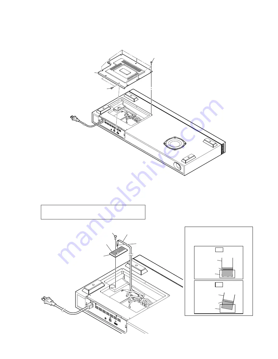
Note:
Follow the disassembly procedure in the numerical order given.
2-2. BOTTOM PANEL
2-3. BT NFC BOARD
1
two screws
(3
u
8 B2)
3
bottom panel
2
seven screws
(3.5
u
12 B)
– Rear bottom view –
Note:
When replacing the BT NFC board or the NFC module, be sure
replace both at the same time.
The BT NFC board or the NFC module cannot replace with single.
1
FFC 16P/MAIN-BT (FFC1)
(XP18)
– Rear bottom view –
2
screw
(3
u
8 B2)
colored line
Insert straight into the interior.
flexible flat
cable
connector
OK
colored line
Insert at a slant.
flexible flat
cable
connector
NG
How to install the flexible flat cable
When installing the flexible flat cable,
ensure that the colored line is parallel
to the connector after insertion.
3
Peel off the adhesive sheet.
4
BT NFC board
terminal side
Содержание HT-XT100
Страница 43: ...MEMO HT XT100 43 ...
Страница 44: ...HT XT100 REVISION HISTORY Ver Date Description of Revision 1 0 2015 02 New ...


