background image

23

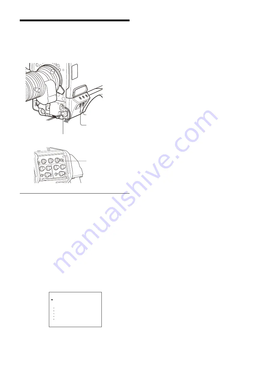
Menu Operations

The menus displayed on the viewfinder screen enable various 
settings of the camera.
The following controls are used to operate the menus.

Starting Menu Operations

To display a menu page

Set the DISPLAY switch from OFF to MENU.
You can also display the menu by setting the DISP/MENU 
switch on the rear panel to MENU.
The menu page that was last operated will be displayed. (If it 
is the first time, the CONTENTS page of the OPERATION 
menu will be displayed.)

To display the TOP MENU screen

If you set the DISPLAY switch from OFF to MENU while 
holding the MENU SEL knob/ENTER button pressed, “TOP” is 
displayed at the upper right corner of the screen. Selecting it 
displays the TOP MENU screen, which lists the available 
menus, and you can select the menus on this screen.

TOP MENU screen

To disable the “TOP” indication

Turn the power off then on again, or set the DISPLAY switch 
from OFF to MENU while holding the STATUS/CANCEL 
switch pressed to CANCEL. This disables the TOP selection.

Available menus

USER menu

This menu can include menu pages selected from among the 
OPERATION, PAINT, MAINTENANCE, FILE, and 
DIAGNOSIS menus, for convenience. Changing, adding, and 
deleting pages can be performed with the USER MENU 
CUSTOMIZE menu.

USER MENU CUSTOMIZE menu

This menu allows you to edit the USER menu.

For details, see “Editing the USER Menu” (page 25).

ALL menu

This menu permits you to control all items of the OPERATION 
menu, PAINT menu, MAINTENANCE menu, FILE menu, and 
DIAGNOSIS menu as a single menu.

OPERATION menu

This menu contains items for camera operators to operate the 
camera. It mainly permits viewfinder, intercom, and switch 
settings.

PAINT menu

This menu contains items for making detailed image 
adjustments while using a waveform monitor to monitor the 
waveforms output from the camera. Support of a video 
engineer is usually required to use this menu.
Although you can also use an external remote control panel or 
master setup unit to set the items on this menu, the menu is 
effective when using the camera by itself outdoors.

MAINTENANCE menu

This menu contains items for performing camera maintenance 
operations, such as changing the system or setting 
infrequently used “paint” items.

FILE menu

This menu is for performing file operations, such as writing or 
clearing the reference file.

DIAGNOSIS menu

This menu enables you to confirm the self-diagnostic 
information.

To select a menu on the TOP MENU screen

1

Turn the MENU SEL knob/ENTER button to align the 
arrow marker (

,

) with the desired menu indication.

2

Press the MENU SEL knob/ENTER button.

The CONTENTS page or the last operated page of the 
selected menu is displayed.

STATUS/CANCEL switch

DISPLAY switch

MENU SEL knob/ENTER button

Press

Turn

DISP/MENU switch

<TOP MENU>

 USER

 USER MENU CUSTOMIZE

 ALL

  OPERATION

  PAINT

  MAINTENANCE

  FILE

  DIAGNOSIS

Содержание HDC5500

Страница 1: ...Color Camera Operating Instructions Before operating the unit please read this manual thoroughly and retain it for future reference HDC5500 2019 Sony Corporation 5 006 578 11 1 ...

Страница 2: ...ts and Settings for Shooting 15 Adjusting the Black Balance and White Balance 15 Setting the Electronic Shutter 17 Setting the Focus Assist Functions 18 Setting the Focus Position Meter Function 19 Setting the Camera Outputs 21 Viewfinder Screen Status Display 22 Menu Operations 23 Starting Menu Operations 23 Selecting Pages 24 Setting Menu Items 24 Editing the USER Menu 25 Menu List 28 Menu Tree ...

Страница 3: ...od of validity of the license indicated by the last character of the name If a character that does not denote a license period of validity is the last character the license will not expire indefinite M Valid for 30 days W Valid for 7 days P Portable license valid for 365 days Portable licenses are available for HZC UHD50 HZC HFR50 software When HKC FB50 or HKC TR37 is installed on the unit 1080I 2...

Страница 4: ...ophone Holder Microphone HDC5500 HDVF EL20 HDVF EL30 Viewfinder MSU 1000 series Master Setup Unit a Supplied with HDLA1500 series Part No A 1128 405 A b Signal transfer up to a maximum of 2 km is possible However the actual transfer distance may vary depending on the system configuration of the cameras and the type of optical fiber cables used c Set the signal transmission rate for the camera to c...

Страница 5: ...ting the camera on a tripod l LED lamp Use as a tally You can switch the function using the menu m Camera number The unit uses electronic paper e ink type camera numbers You can set the camera number using the menu The operating temperature range of the camera number setting is 0 C to 45 C 32 F to 113 F The setting may not be configurable if the temperature range is exceeded Check the temperature ...

Страница 6: ...d as output to the viewfinder or a video monitor when the camera is used in standalone status without connecting a camera control unit When the camera s video signal is being used as output the auto knee function may be used The relationship between the switch setting and the output signal and auto knee function is shown in the table below i WHITE BAL white balance memory selection switch To selec...

Страница 7: ...the operation panel page 8 on the rear of the camera are set to FRONT h RET 2 return video 2 button When this button is pressed the picture on the viewfinder screen changes to the return video signal selected using RET ASSIGNABLE button A B or C on the operation panel on the rear of the camera or using the menu You can also assign other functions to this button using the menu displayed on the view...

Страница 8: ...ting is ENG b LIGHT switch Set to ON to illuminate the operation panel c RET ASSIGNABLE button A B Press the button to switch the function assigned to the button on the REAR FUNCTION ASSIGN page on off When the return function is assigned press the button to display the return video signal on the viewfinder screen while the button is pressed Turn the button to change the assigned function setting ...

Страница 9: ...signal valid only when a camera control unit is connected When a camera control unit having two prompter inputs is connected the signal of input 1 is output from this connector k TEST OUT connector BNC type To output the analog signal This can also output a VBS signal HD SYNC signal or SD SYNC signal whichever is selected in the menu For details about signal settings see Setting the Camera Outputs...

Страница 10: ...rs see Displaying the focus assist indicators page 19 The various parts of the lens used in adjusting the flange focal length are in different positions on different lenses Refer to the operation manual for the particular lens Adjustment procedure 1 Set the iris control to manual and open the iris fully 2 Place a flange focal length adjustment chart approximately 3 meters from the camera and adjus...

Страница 11: ...ng lever to the unlocked position 2 Slide the viewfinder towards the front or rear of the camera to move it into a good viewing position 3 Set the viewfinder front rear positioning lever to the lock position to secure the viewfinder Detaching the viewfinder Loosen the viewfinder left right positioning ring pull the viewfinder stopper then pull out the viewfinder by sliding it in the direction oppo...

Страница 12: ...r and push down the button while pulling the viewfinder toward you as shown in the figure below If the tilt pan angle available for the viewfinder is restricted You can alleviate interference by rotating the camera handle 1 Loosen the handle rotation lock knob 1 of the camera until it turns freely then push the handle rotation release lever 2 to unlock the grip 2 Rotate the handle toward the front...

Страница 13: ...le clamp belt 2 Peel off the cover seal from the camera as shown in the following diagram 3 Secure the cable clamp belt to the camera using the two supplied B3 8 screws 4 1 Release the buckle 2 bundle the cable with the belt 3 then lock the buckle again 5 Adjust the length by pulling down the end of the belt A B Belt bracket Cover seal Screws B3 8 1 2 3 Optical electrical multi cable ...

Страница 14: ...idering the balance of the weight of the camera and the tripod attachment If an inappropriate hole is selected the center of gravity may be off center which may cause the camera to fall over and may cause an injury Check that the size of the selected hole matches that of the screw of the tripod If they do not match the tripod attachment cannot be attached to the tripod securely Attachment procedur...

Страница 15: ...era is used When the camera is used after a long period of disuse When the surrounding temperature changes greatly When the gain value is changed using the setup menus Normally there is no need to adjust the black balance every time the camera is turned on White balance adjustment Always readjust the white balance when lighting conditions change About the viewfinder screen After the process of adj...

Страница 16: ...on switches the available ND filters CLEAR 1 4ND 1 8ND 1 16ND 1 64ND in sequence To select the CC color temperature conversion filter Press the CC filter select button while holding the FILTER LOCAL button depressed Each press of the select button switches the available CC filters cross 3200K 4300K 6300K in sequence 3 Place a white pattern in the same lighting conditions as the subject and zoom in...

Страница 17: ...mode and shutter speed When a camera control unit or a remote control device such as the MSU or RCP series is connected control is performed from the RCP MSU and the switches on the camera are disabled About the shutter modes The shutter modes that can be used with the electronic shutter of the camera and the shutter speeds that may be selected are as follows The values in the table are those with...

Страница 18: ...in the range of 0 to 100 default 25 You can adjust the characteristics of the detail signal with the menu items below CRISP Adjust to eliminate fine portions of the detail signal FREQUENCY Change the detection band of sharp edges FLICKER Turn ON OFF the function to flicker the detail signal which makes it easier to check the signal on a viewfinder screen AREA To limit the area where to display the...

Страница 19: ...tems below SIZE The size of the detection area can be changed If the area size is too large both the subject and the background are included in the area making the indicator display may easily deviate from the subject POSITION Roughly set the position of the detection area POSITION H Finely adjust the position of the detection area in the horizontal direction POSITION V Finely adjust the position ...

Страница 20: ...P Turns the display of the marker name in the adjusted state on off DISPLAY screen only FRAME DISP Turns the display of a color frame adjustment frame on the screen in the adjusted state on off FRAME WIDTH Sets the width of the adjustment frame To configure the marker display settings You can set the marker display using MARKER CONFIG on the FOCUS POSITION METER2 page REG Registers a marker at the...

Страница 21: ...rmation as that being displayed on the viewfinder screen according to the settings of the VF MARKER CHARACTER VF DETAIL ZEBRA etc The ON OFF or other settings for adding information are common to those for the viewfinder The output is synchronized with switching among Y R G and B or switching to a return signal With SD SDI or VBS the output is synchronized only with switching between a return sign...

Страница 22: ...nity Displayed only when a serial communication lens is connected j Battery voltage Displays the input voltage k Focus position meter marker name Displays the marker name of the focus position meter l Setting change adjustment process message area This area is only used when the MESSAGE item of the menu is set to other than OFF m F value Indicates the lens F iris opening value n Shutter ECS Displa...

Страница 23: ...u For details see Editing the USER Menu page 25 ALL menu This menu permits you to control all items of the OPERATION menu PAINT menu MAINTENANCE menu FILE menu and DIAGNOSIS menu as a single menu OPERATION menu This menu contains items for camera operators to operate the camera It mainly permits viewfinder intercom and switch settings PAINT menu This menu contains items for making detailed image a...
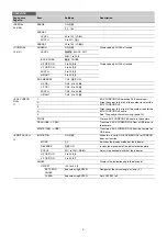
Страница 24: ...switch toward CANCEL before pressing the MENU SEL knob ENTER button the setting will be returned to its previous value To interrupt settings Set the DISPLAY switch to OFF to turn off the menu screen display The setting operation can be restarted by setting the DISPLAY switch back to MENU 4 Press the MENU SEL knob ENTER button The mark changes back to the arrow marker and the new setting will be re...

Страница 25: ... the USER menu and add desired items to the page While the EDIT page contains factory preset items the USER 1 EDIT to USER 19 EDIT pages are all blank in their initial state You can register up to 10 items including blank lines on each of these pages To add items to a page Proceed as follows 1 Set the DISPLAY switch from OFF to MENU while holding the MENU SEL knob ENTER button pressed The TOP MENU...

Страница 26: ...button The EDIT FUNCTION screen appears 2 Select MOVE then press the MENU SEL knob ENTER button The previously displayed page appears again 3 Turn the MENU SEL knob ENTER button to move the arrow marker to the position where you wish to move the item then press the MENU SEL knob ENTER button The item selected in step 1 moves to the position above the item that you selected in step 3 In the above e...

Страница 27: ...SEL knob ENTER button The previously displayed page appears again and the message DELETE OK YES NO appears at the upper right 3 To delete turn the MENU SEL knob ENTER button to move the arrow marker to YES and press the MENU SEL knob ENTER button To move a page Proceed as follows 1 Display the EDIT PAGE screen of the USER MENU CUSTOMIZE menu Turn the MENU SEL knob ENTER button to move the arrow ma...

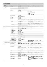
Страница 28: ... CC 5600K IRIS WHITE D EXT GAIN SHUTTER BATT RETURN TALK MESS FOLLOW F AGE ND CC WHITE 5600K GAIN SHUTTER FAN EXT Y TALLY MARKER LEVEL CENTER SAFETY ZONE EFFECT ASPECT MASK SAFETY VF DETAIL CRISP FREQUENCY FLICKER AREA ZOOM LINK COLOR DE RETURN DISABLE TAIL PEAK COLOR CHROMA LEVEL FOCUS NAME FOCUS FORM 01 U04 02 U05 03 U06 04 U02 FOCUS ASSIST ZEBRA INDICATOR MODE LEVEL GAIN OFFSET AREA MARKER SIZE...
Страница 29: ...USB ACTER LEVEL GAIN ASSIGNABLE PinP POSITION SIZE MODE VF ASSIGN VF OUT SW INSIDE RET1 INSIDE RET2 INSIDE CALL 15 U10 17 REAR FUNCTION ASSIGN 16 A PUSH 18 11 13 U01 14 U09 10 U07 12 TRACKER EARPHONE OPERATOR FILE TRACKER RECEIVE SELECT INPUT LEVEL OUTPUT LEVEL L CH OUTPUT LEVEL 2 OUTPUT LEVEL R CH EARPHONE RECEIVE SELECT MIX TALK INTERCOM PGM1 PGM2 PGM3 TRACKER INTERCOM PGM1 PGM2 PGM3 SIDE TONE R...

Страница 30: ...M LIMITER WHT LIMITER BLK CRISP LEVEL DEPEND ABS DETAIL 2 P10 SKIN DETAIL P13 USER MATRIX P14 MULTI MATRIX P15 H V RATIO FREQ MIX RATIO KNEE APT DTL H V MODE INDEPENDENT ABS HD DETAIL P11 DETAIL LEVEL LIMITER M LIMITER WHT LIMITER BLK CRISP LEVEL DEPEND H V RATIO FREQ MIX RATIO KNEE APT ABS 4K DETAIL P12 DETAIL LEVEL LIMITER M LIMITER WHT LIMITER BLK CRISP LEVEL DEPEND H V RATIO FREQ MIX RATIO KNE...

Страница 31: ...ITE SHADING M02 BLACK SHADING M03 OHB MATRIX M04 AUTO IRIS M05 MIC GAIN M08 CAMERA NUMBER M09 AUTO BLACK AUTO WHITE AUTO LEVEL TEST V SAW V PARA H SAW H PARA WHITE V SAW V PARA H SAW H PARA BLK SET BLACK MASTER GAIN OHB MATRIX MATRIX AUTO IRIS WINDOW OVERRIDE IRIS LEVEL APL RATIO IRIS GAIN IRIS CLOSE MIC1 MIC2 LENS1 M06 F NO DISP AL AF DISPLAY LENS2 FOLLOW FOCUS F DROP COMP REMOTE CONTROL AC MAX G...

Страница 32: ...LY TALLY NUMBER NUMBER DISPLAY RESOLUTION FREQUENCY BIT DEPTH COLOR OETF MODE BRIGHTNESS OUTSIDE LED EXTENDER FILTER DISC TALLY GUARD SYNC OUT V PHASE H PHASE OPERATOR FILE F01 SCENE FILE F02 REFERENCE F03 LENS FILE F05 OHB FILE F06 READ USB t CAM WRITE CAM t USB PRESET S CLEAR PRESET FILE TORE PRESET FILE 1 2 3 4 5 01 STORE STANDARD READ USB t CAM WRITE CAM t USB FILE ID CAM CODE DATE STORE FILE ...

Страница 33: ...TATUS D02 ROM VERSION D03 U15 SERIAL NO D04 POWER SUPPLY STATUS D05 CCU t CAM CAM t CCU OHB DPR SY PS TX HOURS METER CAMERA APP OS UPDATER SY PANEL DPR PS TX MODEL NO CABLE LENGTH EFFECTIVE FUNCTION CAM INPUT VOLTAGE CAM CONSUMPTION CABLE LENGTH ...

Страница 34: ...t NORMAL Displayed in the range 0 to 255 no units ABS AUTO Displayed in the units meters or feet set on the lens ABS m Displayed in meters ABS ft Displayed in feet IND 02 U05 ND ON OFF IND Turns the display area see page 22 on off NORMAL Specifies the conditions under which the indication is not to be displayed even if IND is ON By specifying the standard or normal conditions here non standard or ...

Страница 35: ...INK ON OFF 0 to 100 50 COLOR DETAIL ON OFF YELLOW RED BLUE PEAK COLOR ON OFF CHROMA LEVEL 100 50 25 0 RETURN DISABLE ON OFF Selects whether to set VF DETAIL to OFF for RETURN display DYNAMIC FOCUS 05 DYNAMIC FOCUS OFF ON FREQUENCY EXTRA LOW LOW MID HIGH AUTO Sets the bandwidth of the 4K resolution high frequency signal to detect AUTO Displayed when ZOOM LINK is set to ON ZOOM LINK ON OFF MODE1 MOD...

Страница 36: ...isplay time FRAME DISP OFF 1S 3S 5S ON Sets whether to show hide the adjustment frame and sets the display time FRAME WIDTH 1 to 5 2 Sets the width of the adjustment frame MARKER CONFIG REG MKR1 2 3 Execute using ENTER Registers a marker at the current focus position Cannot be registered here if marker registration has been assigned to a dedicated switch DISP MKR1 2 3 OFF ON Shows hides markers Ca...

Страница 37: ...he BOX CURSOR FILE name See To specify a character string page 24 2 3 4 5 STORE Stores a BOX CURSOR FILE name in the camera READ USB t CAM Transfers a BOX CURSOR FILE from a USB drive to the camera WRITE CAM t USB Transfers a BOX CURSOR FILE from the camera to a USB drive SPIRIT LEVEL 12 INDICATOR ON OFF When this is set to ON BOX MEMORY for CURSOR does not function MODE 1 2 Switches the display m...

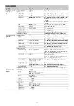
Страница 38: ...RN3 SW INCOM1 INCOM2 EXTENDER D EXTENDER 5600K VF DETAIL SPRIT LEVEL INDICATOR FOCUS ASSIST INDICATOR PinP VF ASSIGN SW1 VF ASSIGN SW2 RET1 SW TOGGLE RET2 SW TOGGLE RET3 SW TOGGLE VTR S S TALLY R TALLY G TALLY Y FAN MAX CURSOR ALL OFF FLAG AWB CALL ZOOM T ZOOM W When HDLA is attached OFF EXTENDER 5600K FAN MAX D EXTENDER PinP FLAG Notes When you turn D EXTENDER ON or OFF noise may be generated Thi...

Страница 39: ...GGLE RET3 SW TOGGLE VTR S S TALLY R TALLY G TALLY Y FAN MAX CURSOR ALL OFF FLAG AWB CALL ZOOM T ZOOM W Assigns functions executed when you press the RET 1 button INSIDE RET2 OFF RETURN1 SW RETURN2 SW RETURN3 SW INCOM1 INCOM2 EXTENDER D EXTENDER 5600K VF DETAIL SPRIT LEVEL INDICATOR FOCUS ASSIST INDICATOR PinP VF ASSIGN SW1 VF ASSIGN SW2 RET1 SW TOGGLE RET2 SW TOGGLE RET3 SW TOGGLE VTR S S TALLY R ...

Страница 40: ...les recording on off While recording the tally lamp lights in red FRONT RET2 OFF RETURN1 SW RETURN2 SW RETURN3 SW INCOM1 INCOM2 EXTENDER D EXTENDER 5600K VF DETAIL SPRIT LEVEL INDICATOR FOCUS ASSIST INDICATOR PinP VF ASSIGN SW1 VF ASSIGN SW2 RET1 SW TOGGLE RET2 SW TOGGLE RET3 SW TOGGLE VTR S S TALLY R TALLY G TALLY Y FAN MAX CURSOR ALL OFF FLAG AWB CALL ZOOM T ZOOM W HANDLE SW1 OFF RETURN1 SW RETU...

Страница 41: ... ROT RET CCU CH SEL VF DETAIL LEVEL VF DETAIL CRISP FOCUS ASSIST IND GAIN Assigns functions executed when you turn RET ASSIGNABLE buttons A B and C The items that can be selected vary depending on the A PUSH B PUSH and C PUSH settings When the PUSH function is OFF OFF When RETURN1 CAM SW RETURN1 CAM SW TOGGLE RETURN2 CAM SW RETURN2 CAM SW TOGGLE RETURN3 CAM SW RETURN3 CAM SW TOGGLE FOCUS POSITION ...

Страница 42: ...ET2 SW TOGGLE RET3 SW TOGGLE VTR S S TALLY R TALLY G TALLY Y FAN MAX CURSOR ALL OFF FLAG AWB CALL ZOOM T ZOOM W RET3 Pin4 OFF RETURN1 SW RETURN2 SW RETURN3 SW INCOM1 INCOM2 EXTENDER D EXTENDER 5600K VF DETAIL SPRIT LEVEL INDICATOR FOCUS ASSIST INDICATOR PinP VF ASSIGN SW1 VF ASSIGN SW2 RET1 SW TOGGLE RET2 SW TOGGLE RET3 SW TOGGLE VTR S S TALLY R TALLY G TALLY Y FAN MAX CURSOR ALL OFF FLAG AWB CALL...

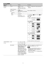
Страница 43: ...DYNAMIC or CARBON cannot be changed 6 0 6 dB Input gain POWER ON OFF ON OFF Settings in With DYNAMIC or CARBON cannot be changed UNBAL ON OFF ON OFF Settings in With CARBON cannot be changed EARPHONE ON OFF LEVEL 34 dBu 40 dBu 46 dBu INTERCOM1 20 INTERCOM1 RECEIVE SELECT SEPARATE MIX Sets the headset audio SEPARATE Set to monaural MIX Set to stereo INTERCOM LEFT RIGHT BOTH When the Line select Rec...

Страница 44: ...eceive MIX select switch on the operation panel is set to MIX this sets the take destination TRACKER 22 TRACKER RECEIVE SELECT SEPARATE MIX Sets the headset audio SEPARATE Set to monaural MIX Set to stereo 1 LR INTERCOM LEFT RIGHT BOTH When the INTERCOM1 Line select Receive MIX select switch on the operation panel is set to MIX menu items ENG and PROD appear instead of this item the setting values...

Страница 45: ...B drive PRESET Execute using ENTER Sets the operator file items to the preset values in internal memory PAINT Page name Page No Item Settings Description SW STATUS P01 FLARE ON OFF GAMMA ON OFF BLK GAM ON OFF KNEE ON OFF WHT CLIP ON OFF DETAIL ON OFF LVL DEP ON OFF SKIN DTL ON OFF MATRIX ON OFF VIDEO LEVEL P02 WHITE R G B 99 to 99 0 R G B and M master values can be independently set M cannot be se...

Страница 46: ... OFF TEST OFF SAW 10STEP KNEE P07 K POINT R G B M 99 to 99 0 R G B and M master values can be independently set Absolute values are displayed in ABS mode except for M master K SLOPE R G B M 99 to 99 0 KNEE ON OFF KNEE MAX ON OFF KNEE SAT 99 to 99 0 ON OFF AUTO KNEE OFF AUTO POINT LIMIT 99 to 99 0 Absolute value is displayed in ABS mode SLOPE 99 to 99 0 Absolute value is displayed in ABS mode WHITE...

Страница 47: ...e is displayed in ABS mode FREQ 99 to 99 0 Absolute value is displayed in ABS mode MIX RATIO 99 to 99 0 Absolute value is displayed in ABS mode KNEE APT 99 to 99 0 Absolute value is displayed in ABS mode ON OFF ABS Highlighted ABS Absolute mode 4K DETAIL P12 DETAIL ON OFF LEVEL 99 to 99 0 Absolute value is displayed in ABS mode LIMITER M 99 to 99 0 LIMITER WHT 99 to 99 0 Absolute value is displaye...

Страница 48: ... to 99 0 G R 99 to 99 0 G B 99 to 99 0 B R 99 to 99 0 B G 99 to 99 0 MATRIX ON OFF PRESET ON OFF SMPTE 240M ITU 709 SMPTE WIDE NTSC EBU ITU 601 CUSTOM1 CUSTOM2 CUSTOM3 CUSTOM4 CUSTOM5 USER ON OFF MULTI ON OFF ADAPTIVE MATRIX OFF ON LEVEL 0 to 7 0 MULTI MATRIX P15 PHASE 0 23 45 68 90 113 135 158 180 203 225 248 270 293 315 338 Selects an axis angle at PHASE for which the multimatrix adjustment is t...

Страница 49: ...ed only when STANDARD is selected Sets the correction gain OFFSET 0 to 99 Enabled only when STANDARD is selected Sets the brightness level that invokes correction ACM TYPE 1 2 3 4 Enabled only when ACM is selected Selects the combination of frames to add More frames are added as the value increases HDR OPERATION P19 HDR MODE OFF LIVE HDR Displays the CCU setting SDR GAIN 0 0 to 15 dB 6 0 dB Enable...

Страница 50: ...te using ENTER Loads 32 scene files from a USB drive to internal memory WRITE CAM t USB Execute using ENTER Writes 32 scene files in the camera s memory to a USB drive FILE ID Max 14 characters Enters a comment for the scene files to be written to a USB drive See To specify a character string page 24 CAM CODE Camera code Display only DATE Date Display only DISSOLVE OFF ON Switches scene files seam...

Страница 51: ...A R G B 99 to 99 0 BLK SET R G B 99 to 99 0 BLACK R G B M 99 to 99 0 MASTER GAIN 6 3 0 3 6 9 12 dB OHB MATRIX M04 OHB MATRIX ON OFF MATRIX ON OFF AUTO IRIS M05 AUTO IRIS ON OFF ON OFF Settings in When a remote control unit panel or a CCU is not connected cannot be changed WINDOW 1 2 3 4 5 6 Selects the auto iris windows The shaded parts indicate the area where light detection occurs OVERRIDE 99 to...

Страница 52: ...on is in progress WAIT Waiting for completion of lens initialization STOP Compensation is turned off for a non applicable lens LENS2 M07 REMOTE CONTROL OFF ON OFF Lens remote control from MSU RCP on off setting Same function as the Active button on the Zoom Focus Control screen of the MSU RCP OFF When lens is not supported CONTROL MODE ZOOM FOCUS FOCUS FOLLOW FOCUS ZOOM FOCUS Control ZOOM and FOCU...

Страница 53: ... to the unit and then select READ LOGO in the menu DELETE LOGO Deletes the configured logo data CALL TALLY M10 CCU CALL OFF ON Selects whether TALLY lights for CALL signal CAM CALL OFF ON HDLA UP TALLY TALLY 0 to 100 50 NUMBER 0 to 100 50 NUMBER DISPLAY AUTO OFF ON OUTSIDE LED Sets the display mode of the LED on the side panel MODE OFF TALLY LIGHT TALLY Function as a tally LIGHT Function as a ligh...

Страница 54: ...K Display only LINK GENLOCK M15 REFERENCE Synchronization status Display only GENLOCK ENABLE DISABLE Not displayed when a CCU is connected STATUS FORMAT PHASE V 1024 to 1023 0 H 1700 to 1700 0 DATE M16 DATE TIME 2000 to 2035 01 to 12 00 to 31 00 to 23 00 to 59 DATE FORMAT 1 Y Mn D 2 Mn D 3 D M Y 4 D M 5 M D Y 6 M D Y Year Mn Month numeric M Month English abbreviation D Day BATTERY ALARM M17 BEFORE...

Страница 55: ...HD TRUNK 1 HD TRUNK HD RETURN IN 2 3840 2160 29 97P 1920 1080 29 97PsF 23 98P 24P SDR fixed OFF 4K 6G SDR HD 1 5G SDR UHD PROMPTER 3840 2160 23 98P 1920 1080 23 98PsF OFF 4K 6G SDR HD 1 5G SDR UHD TRUNK 1 HD TRUNK HD RETURN IN 2 3840 2160 23 98P 1920 1080 23 98PsF 1920 1080 59 94P 50P Other than SDR OFF HD 3G A HDR HD 3G A SDR HD 3G B HDR HD 3G B SDR HD 1 5G SDR UHD PROMPTER 1920 1080 59 94P 1920 ...

Страница 56: ...nk A 1920 1080 59 94P Link A 1920 1080 59 94i Link A B 1920 1080 59 94P 1920 1080 59 94P 1920 1080 59 94i OFF HD 3G A SDR HFR1 HD 3G B SDR HFR1 HD 3G B SDR HFR2 HD 3G A SDR HD 3G B SDR HD 1 5G SDR UHD TRUNK 1 HD TRUNK HD RETURN IN 2 1920 1080 59 94P Link B 1920 1080 59 94P Link B 1920 1080 59 94i Link A B 1920 1080 59 94P 1920 1080 59 94P 1920 1080 59 94i 59 94P 3 50P 3 3 Other than SDR OFF HD 3G ...

Страница 57: ...STORE Execute using ENTER 01 01 to 32 STANDARD Execute using ENTER Reads the standard paint data READ USB t CAM Execute using ENTER Loads 32 scene files from a USB drive to internal memory WRITE CAM t USB Execute using ENTER Writes 32 scene files in the camera s memory to a USB drive FILE ID Max 14 characters Enters a comment for the scene files to be written to a USB drive See To specify a charac...

Страница 58: ... items specific to the CMOS image sensor once stored the values do not need to be stored again if the sensor is reinstalled MATRIX FILE F07 CUSTOM PRESET MATRIX Stores and reads preset files When storing a preset file in camera memory specify the file number STORE FILE Execute using ENTER 1 2 3 4 5 CLEAR ALL Execute using ENTER Clears all the files READ USB t CAM Execute using ENTER Loads five pre...

Страница 59: ...xxx H Displays the total working time ROM VERSION D03 U15 CAMERA APP Vx xx OS Vx xx UPDATER Vx xx PANEL Vx xx Displayed only when HDLA is attached SY Vx xx DPR Vx xx PS Vx xx TX Vx xx SERIAL NO D04 MODEL HDC5500 NO xxxxxxx EFFECTIVE FUNCTION Displayed if any option is installed POWER SUPPLY STATUS D05 Note This display has a margin of error for the display of the electric supply state of the camer...

Страница 60: ...Camera CMOS image sensor phenomena The following phenomena that may occur in images are specific to image sensors They do not indicate a malfunction White flecks Although the image sensors are produced with high precision technologies fine white flecks may be generated on the screen in rare cases caused by cosmic rays etc This is related to the principle of image sensors and is not a malfunction T...

Страница 61: ...SM64X USM W3 series USM8W3 USM16W3 USM32W3 USM64W3 USM128W3 USM R series USM4GR USM8GR USM16GR USM32GR USM64GR USM W series USM8W USM16W USM32W USM64W USM M1 series USM8M1 USM16M1 USM32M1 USM64M1 USM SA3 series USM16SA3 USM32SA3 USM64SA3 USM SA2 series USM16SA2 USM32SA2 USM64SA2 USM SA1 series USM8SA1 USM16SA1 USM32SA1 USM64SA1 USM CA1 series USM16CA1 USM32CA1 USM64CA1 USM L series discontinued US...

Страница 62: ...1 INTERCOM 2 XLR 5 pin female 1 each EARPHONE 4 pole mini jack 1 3 pole stereo 4 pole CTIA standard 4 pole OMTP standard DC IN XLR 4 pin 1 10 5 V to 17 V DC DC OUT 4 pin 1 10 5 V to 17 V DC max 0 5 A This may be limited by the imposed load or input conditions 2 pin 1 10 5 V to 17 V DC max 2 5 A This may be limited by the imposed load or input conditions SDI 1 SDI 2 SDI 3 BNC type 1 each SDI MONI B...

Страница 63: ... 1000 series or later Remote Control Panel CNA 1 Camera Control Network Adapter Notes Always verify that the unit is operating properly before use SONY WILL NOT BE LIABLE FOR DAMAGES OF ANY KIND INCLUDING BUT NOT LIMITED TO COMPENSATION OR REIMBURSEMENT ON ACCOUNT OF THE LOSS OF PRESENT OR PROSPECTIVE PROFITS DUE TO FAILURE OF THIS UNIT EITHER DURING THE WARRANTY PERIOD OR AFTER EXPIRATION OF THE ...

Отзывы: