


HCD-SLK1i/SLK2i
61
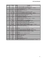
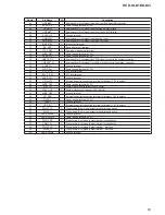
Pin No.
Pin Name
I/O
Description
59
STBY-LED
O
LED drive signal output terminal for ON/STANDBY indicator
“L”: red LED on (STANDBY), “H”: green LED on (ON)
60
P.CONT
O
Power on/off control signal output to the switching regulator “H”: power on
61
FAN-CONTROL
O
Fan motor drive signal output terminal “H”: motor on
62
VCC
-
Power supply terminal (+3.3V)
63
PROTECT FAN
I
Protect signal input from the fan motor
64
VSS
-
Ground terminal
65
(IPOD POWER)
O
Power on/off control signal output terminal for iPod Not used
66
USB POWER
O
Power on/off control signal output terminal for USB section “H”: power on
67
MTK POWER
O
Power on/off control signal output terminal for DVD section “H”: power on
68
ST-TUNED
I
Tuning detection signal input from the tuner (FM) “L”: tuned
69
ST-CE
O
Chip enable signal output to the tuner (FM)
70
ST-DOUT
O
Serial data output to the tuner (FM)
71
ST-CLK
O
Serial data transfer clock signal output to the tuner (FM)
72
ST-DIN
l
Serial data input from the tuner (FM)
73
/SD
I
Shut down signal input from the digital power ampli
fi
er “L”: shut down
74
POWER-KEY
I
Power key input terminal
75
TP INT
I
Interrupt signal input from the TOUCH SENSOR board
76
TP RESET
O
Reset signal output to the TOUCH SENSOR board “L”: reset
77
DSP-DATA
I/O
Two-way data bus with the digital audio processor
78
DSP-CLK
O
Serial data transfer clock signal output to the digital audio processor
79
DSP-VAILD
I
Valid signal input from the digital audio processor
80
DSP-MUTE
O
Muting on/off control signal output to the digital audio processor “L”: muting on
81
DSP-RESET
O
Reset signal output to the digital audio processor “L”: reset
82
DVD 3.3V MONITOR
I
Power (DVD +3.3V) monitor terminal
83 to 85
AD-KEY-2 to
AD-KEY-0
I
Top and front panel key input terminal (A/D input)
86
NO USE
O
Not used
87
TIMER LED
O
LED drive signal output terminal for TIMER indicator “H”: LED on
88
A.STBY LED
O
LED drive signal output terminal for AUTO STANDBY indicator “H”: LED on
89
PLAY LED
O
LED drive signal output terminal for PLAY indicator “H”: LED on
90
PAUSE LED
O
LED drive signal output terminal for PAUSE indicator “H”: LED on
91
NO USE
O
Not used
92
VACS
I
VACS signal input from the digital audio processor
93
NO USE
O
Not used
94
LUX-SENSOR
I
Ambient light sensor input terminal
95
DEST-IN
I
Destination setting terminal
96
AVSS
-
Ground terminal
97
MODEL
I
Model setting terminal
98
VREF
I
Reference voltage (+3.3V) input terminal
99
AVCC
-
Power supply terminal (+3.3V)
100
AD-SWITCH
O
Power on/off control signal output terminal for pull-up of A/D input line “H”: power on


