HCD-DH50R/DH70SWR
59
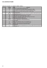
Pin No.
Pin Name
I/O
Description
54
I-SUFFIX
I
Destination setting terminal
55
NC
-
Not used
56
I-KEY3
I
Front panel key input terminal (Except DH50R: AEP/DH70SWR: AEP models only)
57
NC
-
Not used
58
I-KEY1
I
Front panel key input terminal
59
I-AC_DET
I
AC detection signal input terminal
60, 61
NC
-
Not used
62
I-HP_DET
I
Headphone connecting detection signal input terminal “H”: headphone is connected
63
NC
-
Not used
64
I-MIC_DET
I
Microphone connecting detection signal input terminal “L”: microphone is connected
65 to 67
NC
-
Not used
68
O-LED_STBY
O
LED drive signal output terminal for standby indicator “L”: LED on
69
O-CEC_TX_OUT
O
CEC data output to the HDMI OUT connector
70 to 72
NC
-
Not used
73
O-FL_RST
O
Reset signal output to the
fl
uorescent indicator tube driver “L”: reset
74
O-FL_CE
O
Chip select signal output to the
fl
uorescent indicator tube driver
75
O-SYSTEM
POWER_ON
O
System power supply on/off control signal output terminal “H”: power on
76
O-SUBWOOFER_ON
O
Power supply on/off control signal output terminal for subwoofer “L”: power on
77
O-MTK_POWER_ON
O
Power supply on/off control signal output terminal for servo DSP “H”: power on
78
O-TOUCH_SEN-
SOR_RESET
O
Reset signal output to the touch panel block “L”: reset
79
I-TOUCH_SEN-
SOR_INT
I
Interrupt signal input from the touch panel block
80
O-BUZZER
O
Buzzer sound signal output terminal
81
I-RMC
I
SIRCS signal input from the remote control receiver
82
I-ST_TUNED
I
Tuned detection signal input from the tuner (FM/AM) “L”: tuned
83
I-WAKE_UP
I
Wake-up signal input terminal
84
O-FL_DATA
O
Serial data output to the
fl
uorescent indicator tube driver
85
O-ST_CE
O
Chip enable signal output to the tuner (FM/AM)
86
O-FL_CLK
O
Serial data transfer clock signal output to the
fl
uorescent indicator tube driver
87
O-ST_DATA
O
Serial data output to the tuner (FM/AM)
88
O-ST_CLK
O
Serial data transfer clock signal output to the tuner (FM/AM)
89
SI/SO
I/O
Two-way data bus terminal for writing
90
RESET
I
System reset signal input from the reset signal generator “L”: reset
For several hundreds msec. after the power supply rises, “L” is input, then it change to “H”
91
XT2
O
Sub system clock signal output terminal (32.768 kHz)
92
XT1
I
Sub system clock signal input terminal (32.768 kHz)
93
FLMD0
I
Flash memory programming mode setting terminal
94
X2
O
Main system clock signal output terminal (25 MHz)
95
X1
I
Main system clock signal input terminal (25 MHz)
96
REGC
-
External capacitor connecting terminal of regulator output for internal operation
97
VSS
-
Ground terminal
98
EVSS0
-
Ground terminal
99
VDD
-
Power supply terminal (+3.3V)
100
EVDD
-
Power supply terminal (+3.3V)
Содержание HCD-DH50R
Страница 9: ...HCD DH50R DH70SWR 9 ARRANGEMENT OF LEAD WIRE lead wire lead wire ...
Страница 87: ...MEMO HCD DH50R DH70SWR 87 ...

