SONY
62
••
Installation Guide
DVS-7200 • Product Guide
BKDS-8061 Connectors
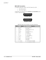
The following BKDS-8061 Shot Box Control Unit connectors are listed:
•
Cascade In Connector
•
Cascade Out Connector
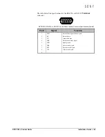
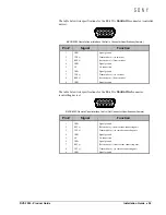
The table below lists specifications for the
Cascade In
and
Cascade Out
control
connectors. Pinouts are identical.
5
4
3
2
1
9
10
11
12
6
7
8
13
14
15
Cascade In — Male
5
4
3
2
1
9
10
11
12
6
7
8
13
14
15
Cascade Out — Female
BKDS-8061 Shot Box Control Unit Cascade In, Out Connector Specifications
Pin #
Signal
Function
1
L; SCLK
Clock (negative logic)
2
GND
Signal ground
3
L; LOAD
Data latch signal (negative logic)
4
GND
Signal ground
5
L; RST
Reset signal (negative logic)
6
GND
Signal ground
7
+5 V
+5 V Power supply
8
+5 V
+5 V Power supply
9
L; LED
LED data (negative logic)
10
GND
Signal ground
11
L; SW
SW data (negative logic)
12
GND
Signal ground
13
GND
Signal ground
14
+5 V (LED)
+5 V Power supply (for LED lighting)
15
+5 V (LED)
+5 V Power supply (for LED lighting)
Содержание DVS-7200
Страница 1: ...SONy DVS 7200 Product Guide ...
Страница 8: ...SONY vi Contents DVS 7200 Product Guide ...
Страница 22: ...SONY 14 Features and Benefits DVS 7200 Product Guide ...
Страница 104: ...SONY 96 Installation Guide DVS 7200 Product Guide ...
Страница 130: ...SO SONy Ny DVS 7200 Product Guide Part Number BC 00603 Revision B ...


