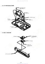


DVP-K370
4-4
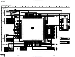
(For printed wiring boards)
•
X
: indicates a lead wire mounted on the component side.
•
x
: indicates a lead wire mounted on the printed side.
•
a
: Through hole.
•
b
: Pattern from the side which enables seeing.
(The other layers' patterns are not indicated.)
THIS NOTE IS COMMON FOR WIRING BOARDS AND SCHEMATIC DIAGRAMS
(In addition to this, the necessary note is printed in each block)
When indicating parts by reference number, please include
the board name.
Caution:
Pattern face side: Parts on the pattern face side seen from
(Side B)
the pattern face are indicated.
Parts face side:
Parts on the parts face side seen from
(Side A)
the parts face are indicated.
(For schematic diagrams)
• All capacitors are in
µ
F unless otherwise noted. pF :
µµ
F.
50V or less are not indicated except for electrolytics and
tantalums.
• All resistors are in ohms, 1/4 W (Chip resistors : 1 /10 W) un-less
otherwise specified.
k
Ω
=1000
Ω
, M
Ω
=1000k
Ω
.
• Caution when replacing chip parts.
New parts must be attached after removal of chip.
Be careful not to heat the minus side of tantalum capacitor, be-
cause it is damaged by the heat.
• All variable and adjustable resistors have characteristic curve B,
unless otherwise noted.
•
2
: non flammable resistor
•
5
: fusible resistor
•
C
: panel designation
•
f
: internal component.
•
C
: adjustment for repair.
•
U
: B+ Line
•
V
: B– Line
• Circled numbers refer to waveforms.
• Voltages are dc between measurement point.
• Readings are taken with a color-bar signals on DVD refer-ence
disc and when playing CD reference disc.
• Readings are taken with a digital multimeter (DC 10MW).
• Voltage variations may be noted due to normal production toler-
ances.
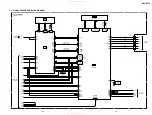
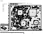
4-2. PRINTED WIRING BOARDS AND SCHEMATIC DIAGRAMS
•
Abbreviation
BR
: Brazilian model
E:HK ; Hong Kong model
E:TW ; Taiwan model
E:SP ; Singapore model
; Malaysia model
; Thailand model
; Philippine model
; Indonesia model
; Vietnum model
Note :
The components identified by mark
0
or dotted
line with mark
0
are critical for safety.
Replace only with part number specified.
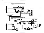
4-3
60.6nsec
29.5nsec
37.4nsec
MB-103
BOARD
2
IC103
qd
,
qg
1
IC104
tf
5.0Vp-p
1.6Vp-p
3
IC103
3
,
8
4.2Vp-p
4
IC103
9
,
q;
40.8nsec
5.0Vp-p
5
IC102
ed
PAL
H
H
5
IC102
ed
NTSC
H
H
H
H
H
AV-63
BOARD
1
IC102
w;
PAL
1
IC102
w;
NTSC
1.4Vp-p
1.0Vp-p
1.9Vp-p
1.4Vp-p
2
IC102
ws
NTSC
1.0Vp-p
2
IC102
ws
PAL
H
1.4Vp-p
3
IC102
wf
,
wl
NTSC
H
1.9Vp-p
4
IC102
ea
NTSC
3
IC102
wf
,
wl
PAL
H
1.9Vp-p
4
IC102
ea
PAL
1.9Vp-p
2.5Vp-p
NTSC:75% COLOR BAR PLAY BACK
PAL :100% COLOR BAR PLAY BACK
125nsec
IF-92
BOARD
1
IC404
3
3.8Vp-p
8.6
µ
sec
4.4
µ
sec
2
ND401
1
,
ys
14.4Vp-p
3
T401
3
21.7Vp-p
w w w . x i a o y u 1 6 3 . c o m
Q Q 3 7 6 3 1 5 1 5 0
9
9
2
8
9
4
2
9
8
T E L
1 3 9 4 2 2 9 6 5 1 3
9
9
2
8
9
4
2
9
8
0
5
1
5
1
3
6
7
3
Q
Q
TEL 13942296513 QQ 376315150 892498299
TEL 13942296513 QQ 376315150 892498299