2-15
DSLR-A100_L2
2-1-6. CCD INCLINATION ADJUSTMENT/REPAIR
Check
1. Use a copy stand, or place a mirror on the wall and adjust the accuracy so that the camera is opposed to its mirror image.
2. Use the AE master lens for inspection.
3. Obtain the tilt angle with the Photoshop, and perform as follows according to the angle:
For the angle above +/–1.0 degree, be sure to repair.
For the angle above +/–0.5 degree and less than +/–1.0 degree, repair according to the user's required level.
For the angle below +/–0.5 degree, re-check and it is within the specification.
Adjustment
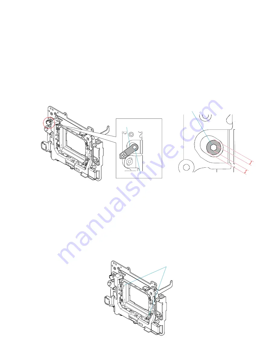
1. Remove the eccentric pin stopper. (Fig. 6-1)
2. Check, and adjust the hexagonal eccentric pin. (Fig. 6-2)
*
The eccentric pin can be rotated 60 degree (CCD tilt 0.42 degree) in clockwise and counterclockwise directions respectively from
the neutral position.
Adjustment exceeding 60 degree is impossible. (Eccentric pin stopper cannot be installed)
If an image tilts toward the lower right, rotate the eccentric pin 60 degree clockwise.
If an image tilts toward the lower left, rotate the eccentric pin 60 degree counterclockwise.
Eccentric Pin Stopper
Eccentric Pin
Fig. 6-1
Eccentric Pin
(neutral Position)
Fig. 6-2
Repair (if the adjusting method failed)
1. Disassemble until the CCD Set can be removed.
2. Cut at two bosses for positional reference and directional reference of the CCD holder and the radiation plate. (Fig. 6-3)
3. Attach an insulation sheet to the terminal of CCD Set. (Prevention of short-circuit with CCD holder)
4. Assemble the CCD Set by shifting it by the amount of play
If an image tilts toward the lower right, shift clockwise the CCD Set by the amount of play.
If an image tilts toward the lower left, shift counterclockwise the CCD Set by the amount of play.
The double-sided adhesive tape on the LPF, if shifted by the amount of play, can be corrected in a range of about +/–0.7 degree
maximum.
In this case, however, prepare the service part "Slider Unit: A-1196-100-A" and modify it as described in step 2 above to make it
as a jig, and then shift the LPF on the jig (for prevention of damage to the Steadyshot Set of user's camera).
5. Assemble up to the exterior.
6. Check the tilt following the checking method.
*
If not /–0.5 degree, replace the "Slider Unit: A-1196-100-A" and recheck.
7. After the repair completed, perform "CCD Aori and Center Adjustment" and "Steadyshot Sensitivity Adjustment".
Fig. 6-3
Two bosses
Содержание DSLR-A100
Страница 23: ...2 17 DSLR A100_L2 Fig 7 1 Fig 7 2 Claw Claw Claw Boss Boss AF Module Flexible FixedTape ...
Страница 59: ...DSLR A100_L2 Schematic diagrams of the AM 001 board is not shown Pages from 4 8 to 4 12 are not shown ...
Страница 73: ...DSLR A100_L2 Printed wiring board of the AM 001 board is not shown Pages 4 26 and 4 27 are not shown ...
Страница 75: ...4 29 DSLR A100_L2 Mounted parts location of the AM 001 board is not shown Page 4 29 is not shown ...
Страница 100: ...DSLR A100_L2 Electrical parts list of the AM 001 board is not shown Page 5 24 to 5 28 are not shown ...


