DSC-N1_L2
2. DISASSEMBLY
2. DISASSEMBLY
2-3
2-4
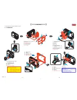
The following flow chart shows the disassembly procedure.
2-1. DISASSEMBLY
1
Flexible board
x1
2
Claw
x3
3
Microphone holder
4
Screw (M1.4x3) (silver)
x5
5
Cabinet (rear) block
1
Insert the flat blade
screw driver.
2
Claw
x1
3
Claw
x2
4
Multi cap
5
Flexible board
x2
6
P2 tapping screw (M1.4x3)
(silver)
x1
7
Remove the SY-MC board.
8
Flexible board
x2
9
SY-MC board.
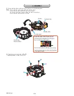
1
P2 screw (M1.4x2.5) (silver)
x5
2
Claw
x2
3
Cabinet (front) block
4
Flexible board
x2
5
Flexible board
x1
6
Lens block
6
5
4
4
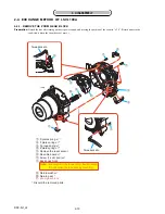
Refer to page 2-1
" Discharging of the ST-129 flexible board's
charging capacitor (C901) ",
when discharging the capacitor.
1
Claw
x1
2
Claw
x2
3
Remove the ST board.
4
Claw
x3
5
Holder (AF)
6
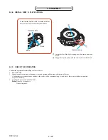
Discharging the Capacitor.
1
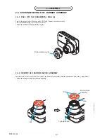
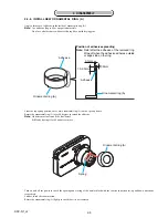
Rotate the ornamental ring (A),
and release the bond.
2
Ornamental ring (A)
3
Insert the tweezers etc..
4
Claew
x3
5
Barrier block assembly
1
2
3
4
4
5
6
7
1
2
3
4
5
3
1
1
2
3
4
6
7
5
8
5
9
1
2
8
3
1
2
4
4
5
1
7
Claw
x1
8
ST board
Note: When you exchange
barrier block assembly
and ornamental ring (A), be sure
to follow the procedure carried on
"2-3. Exchange Method of Barrier
Assembly" (2-7 page).
Position of claws
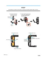
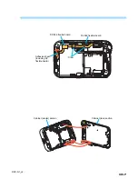
HELP
HELP
HELP
Содержание DSC-N1
Страница 25: ...HELP DSC N1_L2 CCD block 2 1 CCD block Sheet CD CD 585 ...
Страница 26: ...DSC N1_L2 Link Link 3 BLOCK DIAGRAMS OVERALL BLOCK DIAGRAM 2 2 OVERALL BLOCK DIAGRAM 1 2 POWER BLOCK DIAGRAM ...
Страница 45: ...4 45 DSC N1_L2 Waveforms of the SY 138 board are not shown Page 4 43 is not shown ...


