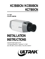
background image

DSC-HX60/HX60V

1-2

1-1.  EXPLODED  VIEWS

1-1-1. Rear Section

ns : not supplied

Ref. No. 

Part No. 

Description

  1 

4-463-246-02 

BOTTOM (470), CABINET

  2 

A-1998-647-A  SW-1006 BOARD, COMPLETE

  3 

4-463-754-01 

BUTTON (CENTER) (470)

  4 

4-463-753-01 

BUTTON (KURUPON) (470)

  5 

X-2588-510-1  CABINET (REAR) ASSY (970C)

  LCD901  A-1955-497-A  SERVICE, PANEL BLOCK ASSY

  #243 

4-412-769-01 

SCREW (M1.4), NEW TRU-STAR, P2

Main Section

(See page 1-3)

#243

ns

ns

ns

#243

5

2

LCD901

1

3

4

#243

Содержание DSC-HX60

Страница 1: ...sian Model E Model Australian Model Hong Kong Model Chinese Model Korea Model Japanese Model 9 834 781 11 DSC HX60 HX60V 2014B08 1 2014 02 注意 修理時に使用するパソコンは ウィルス検出ソフトが常にアップ デートを行っているパソコンを使用してください もし 修理を 行うセット もしくはパソコンがウィルスに感染している事が判 明した場合は ソニーグループ内は社内技術相談窓口に 特約店 様は特約店様専用電話窓口 修理窓口 にご相談ください Model information table Model DSC HX60 DSC HX60V Destination AEP UK RU CH US CND E KR J AEP UK E AUS HK Color s...

Страница 2: ...rinted pattern copper foil may peel away if the heated tip is applied for too long so be careful Unleaded solder is more viscous sticky less prone to flow than ordinary solder so use caution not to let solder bridges occur such as on IC pins etc Be sure to control soldering iron tips used for unleaded solder and those for leaded solder so they are managed separately Mixing un leaded solder and lea...

Страница 3: ...安全点検を サービスのために取外したネジ 部品 配線がもとどお りになっているか またサービスした個所の周辺を劣化 させてしまったところがないかなどを点検し 安全性が 確保されていることを確認して下さい 5 チップ部品交換時の注意 取外した部品は再使用しないで下さい タンタルコンデンサのマイナス側は熱に弱いため交換 時は注意して下さい 6 フレキシブルプリント基板の取扱いについて 半田こてのこて先温度は約350 に設定してくださ い 同一パターンに何度もコテ先を当てないで下さい 3 回以内 パターンに力が加わらないよう注意して下さい サービス 点検時には次のことにご注意ください 無鉛半田について 本機には無鉛半田が使用されています 無鉛半田を使用している基板には 無鉛 Lead Free を意味 するレッドフリーマークがプリントされています 注意 基板サイズによっては 無鉛半田を使用してい...

Страница 4: ... 本体質量 CIPA準拠 約 272 g バッテリー NP BX1 メモリースティック PRO デュオを含む ENGLISH JAPANESE Input and Output connectors HDMI connector HDMI micro jack Multi Micro USB Terminal USB communication USB communication Hi Speed USB USB 2 0 Supports Micro USB compatible device Screen LCD screen 7 5 cm 3 0 type TFT drive Total number of dots 921 600 dots Power general Power Rechargeable battery pack NP BX1 3 6 V AC Adaptor AC...

Страница 5: ...lacer que par une pièce portant le numéro spécifié CAUTION Danger of explosion if battery is incorrectly replaced Replace only with the same or equivalent type Dispose of used batteries according to the instructions 注意 如果电池更换不当会有爆炸危险 只能用同样类型或等效类型的电池来更换 务必按照说明处置用完的电池 Color Indication of Appearance Parts Example SILVER Cabinet s Color Silver Parts Color JAPANESE 使用上の注意 ここに記載されている部品は 補修用部品であるため 回路図及び...

Страница 6: ... BOTTOM 470 CABINET 2 A 1998 647 A SW 1006 BOARD COMPLETE 3 4 463 754 01 BUTTON CENTER 470 4 4 463 753 01 BUTTON KURUPON 470 5 X 2588 510 1 CABINET REAR ASSY 970C LCD901 A 1955 497 A SERVICE PANEL BLOCK ASSY 243 4 412 769 01 SCREW M1 4 NEW TRU STAR P2 Main Section See page 1 3 243 ns ns ns 243 5 2 LCD901 1 3 4 243 ...

Страница 7: ... A B D C D 243 243 243 53 51 52 54 55 ns Lens Block Section See page 1 6 Note 1 BTH Block Section See page 1 4 Upper Block Section See page 1 5 243 Note 1 Hold the Lens Block at the center of both sides Do not hold the following part Hold here PRECAUTIONS WHEN HOLDING THE LENS BLOCK Lens Barrier Very weak Focus Unit Very weak Zoom Motor Very weak Focus Lens Very weak Connector 55 4 484 574 01 HOLD...

Страница 8: ... 2010 FLEXIBLE BOARD COMPLETE 105 4 463 244 02 PLATE 470 STRAP Ref No Part No Description 106 4 463 243 01 PLATE 470 HD 107 4 420 625 01 SCREW TRIPOD 350 BT001 1 756 710 12 LITHIUM RECHARGEABLE BATTERY BT901 1 780 826 11 TERMINAL BOARD BATTERY C901 1 118 284 11 CAP ALUMINIUM ELECT 55μF 330V C902 1 118 285 11 CAP ALUMINIUM ELECT 35μF 330V BT901 BT001 C901 C902 ns ns ns ns ns ns ns ns 101 104 105 10...

Страница 9: ...K ST BLOCK ASSY including FL 2000 flexible board 164 A 1998 649 A ST 1021 FLEXIBLE BOARD COMPLETE 166 4 463 241 03 HOLDER 470 ST SPEAKER 167 4 468 985 21 PLATE MODE 470 Note 1 ANT001 A 1975 721 A ANTENNA SERVICE NFC Note 2 SP901 1 858 343 71 LOUDSPEAKER 1 0CM 28 3 348 998 61 SCREW M1 4X4 TAPPING PAN 140 2 635 562 01 SCREW M1 7 284 4 433 882 21 TAPPING 1 4 ECOLOGY Note 2 140 28 28 28 28 SP901 ANT00...

Страница 10: ...ER Z 211 8 848 910 01 DEVICE LENS LSV 1660A BK Note 1 2 212 A 1940 465 A CD 1005 FLEXIBLE BOARD COMPLETE including CMOS imager 213 4 476 409 01 PLATE MR 176 3 947 504 31 SCREW M1 2 258 4 299 468 11 SCREW TAPPING UB1 2 CH 201 203 211 Note 1 2 212 204 213 205 206 207 208 209 210 202 258 258 including CMOS imager 176 ns ns ns ns Note 1 Hold the Lens Block at the center of both sides Do not hold the f...

Страница 11: ...t No Description F0100 1 576 415 31 FUSE 2A 32V F0101 1 576 842 31 FUSE 0 63A 32V F0102 1 576 843 31 FUSE 0 8A 32V F5650 1 576 415 31 FUSE 2A 32V F5650 5 0V F0101 4 2V F0100 F0102 4 2V SY 1032 BOARD SIDE A SY 1032 BOARD SIDE B Primary side ...

Страница 12: ...ry Pack NP BX1 J J 8 022 359 31 Rechargeable Battery Pack NP BX1 UC US CND 8 022 359 50 Rechargeable Battery Pack NP BX1 CE EXCEPT US CND CH J 8 022 359 71 Rechargeable Battery Pack NP BX1 CN CH Ref No Part No Description 907 4 529 918 11 Instruction Manual ENGLISH 907 4 529 918 21 Instruction Manual ENGLISH SPANISH 907 4 529 918 31 Instruction Manual ENGLISH FRENCH 907 4 529 918 41 Instruction Ma...

Страница 13: ... 1 2 Self diagnosis Display When problems occur while the unit is operating the LCD screen shows a 4 digit display consisting of an alphabet and numbers which blinks at 3 2 Hz This 5 character display indicates the re paired by block in which the problem occurred and detailed code of the problem 2 TROUBLE SHOOTING 0 0 3 2 C Repaired by Refer to 2 1 3 Self diagnosis Code Table Indicates the appropr...

Страница 14: ...E 6 1 3 0 Reset position detection error on the stepper iris ini tializing Turn the power off and on again E 6 2 0 2 Abnormality of IC for steadyshot Turn the power off and on again E 6 2 1 0 Lens initializing failure Turn the power off and on again E 6 2 1 1 Lens overheating PITCH Turn the power off and on again E 6 2 1 2 Lens overheating YAW Turn the power off and on again E 6 2 2 0 Abnormality ...

Страница 15: ...g a board that contains the main IC CPU the IC s unique number MAC address must be reloaded Perform the following procedure to reload the IC s unique number MAC address Note Perform the following operations after all work has been done 1 Download the latest version Adjust Manual 2 Install the downloaded Adjust Manual 3 Start the Adjust Manual and execute Wireless LAN Setting MAC Address on the ADJ...

Страница 16: ...ntact end Do not apply excessive force to the gilded flexible board Cut and remove the part of gilt which comes off at the point Be careful or some pieces of gilt may be left inside The proper way to disconnect a connector is to grab the con nector instead of the wires If you pull on the wires they might be broken The proper way to connect a connector is to grab the connector instead of the wires ...

Страница 17: ...s and a password for Wi Fi connection is displayed Send to Smartphone Enter SSID DIRECT XXXX DSC XXXX Password XXXXXXXX Device Name DSC XXXX Wi Fi Operate smartphone to connect to this device via Wi Fi Cancel 5 Confirm on the personal computer that the unit is detected as a connectable wireless network 6 To further confirm that the unit is connectable connect the unit to the personal computer and ...

Страница 18: ...rs to prevent any abnormal situation caused by high voltage setting of the flash is changed automatically to disabling charge and flash setting After fixing this setting needs to be deactivated Method for Initializing the Flash Error Code Reset Flash Error using the Flash Error Repair Tool Ver_ exe ENGLISH ...

Страница 19: ...換した場合 IC の固有番号 MAC アドレス を取り込み直す必要があります 下記の作業を実施して IC の固有番号 MAC アドレス を取り込み直してください Note 下記の操作は全ての作業を実施した後に行ってください 1 最新版のAdjust Manualをダウンロードする 2 ダウンロードしたAdjust Manualをインストールする 3 Adjust Manualを起動し ADJUSTタブにある Wireless LAN Setting MAC Address を実施する 4 セット本体を下記のように操作し SSID PWリセットを行う ワイヤレス SSID PWリセット 確認 対象となる部品 SW 1006 BOARD COMPLETE SY 1032 BOARD COMPLETE SERVICE Note Adjust manual 内の DATA タブにある ADJUST...

Страница 20: ...絶縁面 コネクター フレキシブル基板 B フラットケーブルおよびフレキシブル基板の端子面に欠け 折れ等がないことを確認してください 金メッキされているフレキシブル基板には 強い負担をかけ ないでください 先端の剥がれたメッキ部はカットして 除去してください メッキ破片がコネクター内に残って いる場合もあるので注意してください コネクターを取り外す際に 線材部 極細 を持って引っ張る と断線する恐れがありますので 絶対に線材部 極細 を持っ て引っ張らないでください 線材部 極細 を押さえながらコネクターを差し込むと 線材 部 極細 が断線する恐れがありますので 絶対に線材部 極細 には負担をかけないでください JAPANESE 3 3 ストロボ用充電コンデンサの放電について ストロボ用充電コンデンサは非常に高い電圧で充電されています そのため ストロボ用充電用コンデンサに手を触れた場合には...

Страница 21: ...この画像 を選ぶ 4 Wi Fi準備が完了すると以下の画面に切り替わり Wi Fi接続のためのパスワードが表示される SSID DIRECT XXXX DSC XXXX パスワード XXXXXXXX 機器名称 DSC XXXX スマートフォン転送 スマートフォンを操作して 本機にWi Fi接続してください Wi Fi キャンセル 決定 5 パソコン側で接続可能なワイヤレスネットワークとして 本機が検出されることを確認する 6 さらに接続可能なことを確認したい場合には本機とパソコンを接続後 通知領域に表示されているアイコンから 現在の接 続先 をダブルクリックし ワイヤレスインターネットアクセスの欄に本機が表示される事を確認する DIRECT xxxx DSC HX60V JAPANESE ...

Страница 22: ... 3 8 JAPANESE 3 5 フラッシュエラー発生時の対処法 本機はフラッシュエラー 自己診断コードE 91 01 が発生した場合 高電圧による異常を防止するために自動的にフラッシュ 充電および発光禁止の設定になります フラッシュエラー発生後はエラーの解除を行う必要があります フラッシュエラーの解除方法 Flash Error Repair Tool Ver exe を使用して Flash Error を解除してください ...

Страница 23: ...y q Cabinet Front 3 SW 1006 Board 6 SY 1032 Board 7 Lens Block 4 Panel Block Assy 5 Main Frame 2 Cabinet Bottom CD 1005 Flexible Board LF 2038 Flexible Board 8 BTH Block BT 2010 Flexible Board 9 Upper Block FL 2000 Flexible Board RL 1011 Board RL 1012 Flexible Board SH 1006 Flexible Board ST 1021 Flexible Board SW 1017 Flexible Board ...

Страница 24: ...A MOVIE MENU Fn DELETE CONTROL WHEEL SHUTTER ZOOM MULTI CN9000 S BT901 BATTERY TERMINAL C901 C902 CHARGING CAPACITOR C902 C901 BT001 LITHIUM BATTERY SP901 SPEAKER RED BLU FL 2000 FLEXIBLE BOARD 1 14 FLASH UNIT ANT001 NFC ANTENNA 1 1 27 1 20 20 1 27 MIC001 MICROPHONE R MIC002 MICROPHONE L 17 18 1 6 15 5 24 1 1 24 1 29 26 30 27 28 CN4101 CN4107 CN2001 1 2 38 39 1 1 51 1 25 2 50 51 1 26 2 27 20 1 22 ...

Страница 25: ...x 8 3 SW 1006 Board Claw x 2 Connector x 1 Refer to Notes onAssembling the Button Center and the Button KURUPON when assembling page 4 6 4 Panel Block Assy Connector x 2 Refer to Notes on Assembling the LCD unit when assembling page 4 6 243 M1 4 X 3 5 Black 4 412 769 01 3 5 1 4 Main Section See page 4 4 243 1 243 2 243 1 1 4 2 Claws Claws Claws Claws 243 1 3 Claws Multi Lid ...

Страница 26: ...T 2010 Flexible Board Note 高電圧の警告 Short circuit the terminals of the flash capacitor with a Short Jig for approximately 10 seconds Refer to the Service Note for a Short Jig Note Warning of high voltage ストロボ用充電コンデンサの端子間に ショート治具を接続し 約10秒間 放電 を行ってください ショート治具についてはサービスノート を参照してください Short Jig ショート治具 The charging capacitor for the flash ストロボ用充電コンデンサ 2 8 7 1 3 Lens Block Section 5 BTH Block Section 6 Uppe...

Страница 27: ...ST Cover 284 x 2 Push the Flash pop up button 6 ST Block Assy 28 x 1 7 Loudspeaker 1 0cm Solder x 2 8 SH 1006 Board Remove the Mic Holder from the Cabinet Upper then remove the SH 1006 board 9 Cabinet Upper 28 M1 4 X 4 0 Tapping Silver 3 348 998 61 1 4 4 0 140 M1 7X 2 0 Black 2 635 562 01 2 0 1 7 284 M1 4 X 3 0 Tapping Black 4 433 882 21 3 0 1 4 140 28 28 28 28 284 RL 1012 Flexible Board Insulatin...

Страница 28: ...the Flexible Board of the LCD unit is arranged within the SY 1032 Board area SY 1032 Board Flexible Board of the LCD unit 3 Notes on Assembling the SY 1032 Board Be sure install the SY 1032 Board to main unit after install the SW 1017 Flexible Board to the SY 1032 Board SW 1017 Flexible Board SY 1032 Board 1 2 4 Notes on Assembling the RL 1011 Board Rotary plate RL 1011 Board Cabinet Upper Assy Ma...

Страница 29: ...oard BTH Assy 2 Connect the BT 2010 Flexible Board to the Terminal Battery Board BT 2010 Flexible Board Terminal Battery Board BTH Assy 3 Set the Lithium Rechargeable Battery Lithium Rechargeable Battery 4 Set the claws and bosses Bosses Claws Claws 6 Notes on Assembling the Upper Block Route the speaker harnesses Cabinet Front Speaker Upper Block ...

Страница 30: ...end 2 Detach the battery 3 Pour a solvent such as alcohol to two gaps A of the Ornamental Ring A with tweezers or a fine tipped stick as shown below 4 Heat the Ornamental Ring A with a drier 5 Turn the Ornamental Ring A clockwise and counterclockwise to detach it A Ornamental Ring A Solvent Tweezers Drier 6 Disengage the four claws and remove the Barrier Assy Claws Barrier Assy ...

Страница 31: ...ier Assy Claws Barrier Assy Barrier Assy 2 Attach two Barrier Tapes so that the end of each tape comes to the dent Note Attach Barrier Tapes carefully so that they do not wrinkle 3 Attach the Ornamental Ring A and push it gently Ornamental Ring A Barrier Tapes Barrier Tapes ...

Страница 32: ...r FPC Retainer Z Retainer Claw 4 Unsolder the DC Motor Worm Assy at two locations shown below 5 Disconnect the flexible board from the connector on the LF 2038 Flexible Board Solders Connector Disconnect the flexible board DC Motor Worm Assy LF 2038 Flexible Board 6 Disconnect the three sensors on the LF 2038 Flexible Board 7 Remove the five screws to detach the Rear Lens Assy Sensor Screws LF 203...

Страница 33: ...DC Motor Worm Assy Screws DC Motor Worm Assy Gear B Gear A Gear WH 12 Insert the Gear B and turn it clockwise to set the lens unit in the TELE end state Note Turn the Gear B to the maximum 13 Release the flexible board from the boss and pull the Flexible Board out of the hole Boss Flexible Board Hole Flexible Board Gear B ...

Страница 34: ...e lens unit in the retracted state and then remove the Gear B Note Turn the Gear B to the maximum Gear B Gear B 15 Remove the 3 Group Frame Block Assy and the Core Unit_1 from the Fixed Barrel 3 Group Frame Block Assy Core Unit_1 Fixed Barrel Core Unit_1 Fixed Barrel ...

Страница 35: ...ive Gear Barrel Assy Drive Gear Barrel Linear Motion Cam Barrel 18 Turn the rear edge of Core Unit_3 counterclockwise to extend the Front Assy Note For removing the Barrier Assy refer to 1 Ornamental Ring A or Barrier Assy Replacing Method Barrier Ring Rear edge of Core Unit_3 Front Assy Note For removing the Ornamental Ring A and the Barrier Assy refer to 1 Ornamental Ring A or Barrier Assy Barri...

Страница 36: ...direction of arrow to detach the Front Assy from the Linear Guide Barrel_A Note When detaching the Front Assy do not stimulate the white part shown below If it is stimulated it may pop out by the action of the spring About 12 Approx 4mm Linear Guide Barrel_A Linear Guide Barrel_A Rear edge of Front Assy Front Assy Spring White part 22 Turn the Barrier Frame to remove it from the 1 Group Frame Bloc...

Страница 37: ...nce due to the spring tension it can be detached by turning it overcoming the resistance Cam Barrel Core Unit_4 24 Unhook the 2G Spring at two locations and remove the 2 Group Frame Block Assy from the Linear Guide Barrel_B Tweezers 2 Group Frame Block Assy 2 Group Frame Block Assy Linear Guide Barrel_B 2G Spring 2G Spring ...

Страница 38: ...g with tweezers and hook them to the 2 Group Frame Block Assy 2 Group Frame Block Assy 2 Group Frame Block Assy Linear Guide Barrel_B Vertical groove Vertical grooves Tweezers Cabinet number Cabinet number Projections 2G Spring 2G Spring 3 While matching the cabinet numbers of the Cam Barrel and the Linear Guide Barrel_B insert the Linear Guide Barrel_B into the Cam Barrel turning the Linear Guide...

Страница 39: ...sy into the Linear Guide Barrel_A Barrier Frame Arrow mark Barrier Frame 1 Group Frame Block Assy Triangle mark Concave Convex Convex position set 1 Group Frame Block Assy Three square marks Three square marks 1 Group Frame Block Assy 1 Group Frame Block Assy Linear Guide Barrel_A Cabinet number 7 Slightly turn the rear edge of Barrier Frame in the direction of arrow to extend the Barrier Frame Li...

Страница 40: ...o 1 Ornamental Ring A or Barrier Assy Replacing Method 11 While matching the concave of the Drive Gear Barrel Assy with the diamond mark on the Linear Motion Cam Barrel insert the Linear Motion Cam Barrel into the Drive Gear Barrel Assy 12 Turn the Linear Motion Cam Barrel until the gear end of the Drive Gear Barrel Assy and the semicircular cutout of the Linear Motion Cam Barrel come to the posit...

Страница 41: ...he diamond mark on the Drive Gear Barrel Assy with the triangle mark on the Core Unit_2 14 While matching the semicircular cutout of the Core Unit_1 with the gear B mounting portion of the Fixed Barrel insert the Core Unit_1 into the Fixed Barrel Core Unit_1 Semicircular cutout Gear B mounting portion Fixed Barrel Match the semicircular cutout of the Core Unit_1 with the gear B mounting portion of...

Страница 42: ...board Flexible board 3 Group Frame Block Assy Fixed Barrel Core Unit_1 17 Turn the Gear B clockwise to set the lens unit in the TELE end state Note Turn the Gear B to the maximum Gear B 18 Pass the flexible board through the hole in the Fixed Barrel and fix the flexible board to the groove and the boss Boss Groove Flexible board Hole Fixed Barrel ...

Страница 43: ...he DC Motor Worm Assy with the boss and secure it with two screws 21 Install Gear WH Gear A and then Gear B Screws Boss DC Motor Worm Assy Gear B Gear A Gear WH DC Motor Worm Assy 22 Secure the Rear Lens Assy with five screws 23 Connect the three sensors on the LF 2038 Flexible Board Sensor Screws Screws Sensors LF 2038 Flexible Board Rear Lens Assy ...

Страница 44: ...sy at two locations shown below to secure the LF 2038 Flexible Board to the DC Motor Worm Assy Solders DC Motor Worm Assy 27 Fix the FPC Retainer to the two projections and then to the claw 28 Fix the FG Retainer to the boss and then to the claw 29 Fix the Z Retainer to the two projections and then to the claw Claw Claw Boss Claw FPC Retainer Z Retainer Projections Projections FG Retainer 30 Perfo...

Страница 45: ...onfirm the contents of them Note 1 Be sure to install Adjust station first Note 2 To perform Destination Data Write for this model the Adjust manual of the DSC WX50 series must have been installed Install the Adjust manual of the DSC WX50 series in advance JAPANESE これらの機種で調整を行なうには アジャストマニュアルとアジャストステーションが必要です アジャストステーションとは 機種別のアジャストマニュアルを起動するためのソフトウェアです アジャストステーションのインストーラと一緒に インストレーションマニュアルが付いていますの...

Страница 46: ...Ver Date History Contents S M Rev issued 1 0 2014 02 Official Release Revision History ...

Отзывы: