


5-45
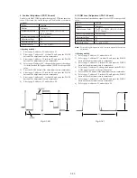
3. S VIDEO OUT Chroma Level Adjustment
(VC-217 board)
Mode
Camera
Subject
Arbitrary
Measurement Point
Chroma signal terminal of S VIDEO
jack (75
Ω
terminated)
External trigger: Y signal terminal of
S VIDEO jack
Measuring Instrument
Oscilloscope
Adjustment Page
C
Adjustment Address
26, 27
Specified Value
Cr level:
A = 714 ± 14mV(NTSC)
A = 700 ± 14mV(PAL)
Cb level:
B = 714 ± 14mV(NTSC)
B = 700 ± 14mV(PAL)
Burst level: C = 286 ± 6mV(NTSC)
C = 300 ± 6mV(PAL)
Adjusting method:
1)
Select page: 0, address: 01, and set data: 01.
2)
Select page: 2, address: 35. After note down the data of this
address, set data: 01 to the address.
3)
Select page: 3, address: 0C, set data: 02, and press the PAUSE
button of the adjustment remote commander.
4)
Select page: C, address: 26, change the data and set the Cr
signal level (A) to the specified value.
5)
Press the PAUSE button of the adjustment remote commander.
6)
Select page: C, address: 27, change the data and set the Cb
signal level (B) to the specified value.
7)
Press the PAUSE button of the adjustment remote commander.
8)
Check that the burst signal level (C) is satisfied the specified
value.
9)
Select page: 3, address: 0C, set data: 00, and press the PAUSE
button of the adjustment remote commander.
10) Select page: 2, address: 35. and set the data that is noted down
at step 2).
11) Select page: 0, address: 01, and set data: 00.
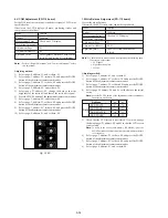
4. AV OUT Y, Chroma Level Check (VC-217 board)
Mode
Camera
Subject
Arbitrary
Measurement Point
Video terminal of AUDIO/VIDEO
jack (75
Ω
terminated)
Measuring Instrument
Oscilloscope
Specified Value
Sync level: A = 286 ± 18mV(NTSC)
A = 300 ± 18mV(PAL)
Burst level: B = 286 ± 18mV(NTSC)
B = 300 ± 18mV(PAL)
Adjusting method:
1)
Select page: 2, address: 35. After note down the data of this
address, set data: 01 to the address.
2)
Select page: 3, address: 0C, set data: 02, and press the PAUSE
button of the adjustment remote commander.
3)
Check that the sync signal level (A) satisfies the specified value.
4)
Check that the burst signal level (B) satisfies the specified value.
5)
Select page: 3, address: 0C, set data: 00, and press the PAUSE
button of the adjustment remote commander.
6)
Select page: 2, address: 35. and set the data that is noted down
at step 1).
Fig. 5-3-8.
Fig. 5-3-9.
H
C
A
0.28
µ
sec (NTSC)
0.23
µ
sec (PAL)
B
0.28
µ
sec (NTSC)
0.23
µ
sec (PAL)
H
B
A
Содержание Digital Handycam DCR-TRV10
Страница 10: ...1 2 ...
Страница 11: ...1 3 ...
Страница 12: ...1 4 ...
Страница 13: ...1 5 ...
Страница 14: ...1 6 ...
Страница 15: ...1 7 ...
Страница 16: ...1 8 ...
Страница 17: ...1 9 ...
Страница 18: ...1 10 ...
Страница 19: ...1 11 ...
Страница 20: ...1 12 ...
Страница 21: ...1 13 ...
Страница 22: ...1 14 ...
Страница 23: ...1 15 ...
Страница 24: ...1 16 ...
Страница 25: ...1 17 ...
Страница 26: ...1 18 ...
Страница 27: ...1 19 ...
Страница 28: ...1 20 ...
Страница 29: ...1 21 ...
Страница 30: ...1 22 ...
Страница 31: ...1 23 ...
Страница 32: ...1 24 ...
Страница 33: ...1 25 ...
Страница 34: ...1 26 ...
Страница 35: ...1 27 ...
Страница 36: ...1 28 ...
Страница 37: ...1 29 ...
Страница 38: ...1 30 ...
Страница 39: ...1 31 ...
Страница 40: ...1 32 ...
Страница 41: ...1 33 ...
Страница 42: ...1 34 ...
Страница 43: ...1 35 ...
Страница 44: ...1 36 ...
Страница 45: ...1 37E ...
Страница 56: ...DCR TRV8 TRV8E TRV10 TRV10E SECTION 3 BLOCK DIAGRAMS 3 1 3 2 3 3 3 4 3 1 OVERALL BLOCK DIAGRAM TRV8 TRV8E ...
Страница 57: ...DCR TRV8 TRV8E TRV10 TRV10E 3 5 3 6 3 7 3 8 3 2 OVERALL BLOCK DIAGRAM TRV10 TRV10E ...
Страница 58: ...DCR TRV8 TRV8E TRV10 TRV10E 3 3 POWER BLOCK DIAGRAM 3 9 3 10 3 11 3 12E ...
Страница 180: ... 264 OPTICAL AXIS FRAME Take a copy of OPTICAL AXIS FRAME with a clear sheet for use ...


