


5-21
5. Flange Back Adjustment
(Using Flange Back Adjustment Chart and Subject
More Than 500m Away)
The inner focus lens flange back adjustment is carried out
automatically. In whichever case, the focus will be deviated during
auto focusing/manual focusing.
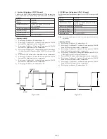
5-1. Flange Back Adjustment(1)
Subject
Flange back adjustment chart
(2.0 m from the front of the lens)
(Luminance: 350 ± 50 lux)
Measurement Point
Check operation on TV monitor
Measuring Instrument
Adjustment Page
F
Adjustment Address
24 to 29, 36 to 3D, 5D
Specified Value
Upper digit: 0 to 9
Lower digit: 0 to 9
Switch setting:
NIGHT SHOT .................................................................. OFF
Adjusting method:
1)
Check that at both the zoom lens TELE end and WIDE end,
the center of the chart for the flange back adjustment and center
of the exposure screen coincide.
2)
Select page: 0, address: 01, and set data: 01.
3)
Check that the data of page: F, address: 24 to 29, 36 to 3D is
the initial value (See table below).
4)
Select page: 6, address: 02, and check that the data is “00”.
5)
Select page: 6, address: 01, set data: 13, and press the PAUSE
button of the adjustment remote commander.
6)
Select page: 6, address: 01, set data: 15, and press the PAUSE
button.
(The adjustment data will be automatically input to page: F,
addresses: 24 to 29, 36 to 3D, 5D.)
7)
Select page: 6, address: 02, and check that the data is “01”.
8)
Select page: F, address: 3D, and check that the upper digit and
lower digit of the data satisfies each specified value.
Processing after Completing Adjustments:
1)
Select page: 6, address: 01, set data: 00, and press the PAUSE
button.
2)
Perform “Flange Back Adjustment (2)”.
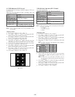
5-2. Flange Back Adjustment (2)
Perform this adjustment after performing “Flange Back Adjustment
(1)”.
Subject
Subject more than 500m away
(Subjects with clear contrast such as
buildings, etc.)
Measurement Point
Check operation on TV monitor
Measuring Instrument
Adjustment Page
F
Adjustment Address
24 to 29, 36 to 3D, 5D
Switch setting:
NIGHT SHOT .................................................................. OFF
Adjusting method:
1)
Set the zoom lens to the TELE end and expose a subject that is
more than 500 m away (subject with clear contrast such as
building, etc.). (Nearby subjects less than 500 m away should
not be in the screen.)
2)
Select page: 0, address: 01, and set data: 01.
3)
Select page: 6, address: 02, and check that the data is “00”.
4)
Select page: 6, address: 01, set data: 13, and press the PAUSE
button of the adjustment remote commander.
5)
Place a ND filter on the lens so that the optimum image is
obtain.
6)
Select page: 6, address: 01, set data: 29, and press the PAUSE
button.
(The adjustment data will be automatically input to page: F,
addresses: 24 to 29, 36 to 3D, 5D.)
7)
Select page: 6, address: 02, and check that the data is “01”.
Processing after Completing Adjustments:
1)
Select page: 6, address: 01, set data: 00, and press the PAUSE
button.
2)
Select page: 0, address: 01, and set data: 00.
3)
Perform “Flange Back Check”.
Address
24
25
26
27
28
29
36
Data
51
19
22
20
93
13
00
Address
37
38
39
3A
3B
3C
3D
Data
00
46
00
19
00
2A
00
Содержание Digital Handycam DCR-TRV10
Страница 10: ...1 2 ...
Страница 11: ...1 3 ...
Страница 12: ...1 4 ...
Страница 13: ...1 5 ...
Страница 14: ...1 6 ...
Страница 15: ...1 7 ...
Страница 16: ...1 8 ...
Страница 17: ...1 9 ...
Страница 18: ...1 10 ...
Страница 19: ...1 11 ...
Страница 20: ...1 12 ...
Страница 21: ...1 13 ...
Страница 22: ...1 14 ...
Страница 23: ...1 15 ...
Страница 24: ...1 16 ...
Страница 25: ...1 17 ...
Страница 26: ...1 18 ...
Страница 27: ...1 19 ...
Страница 28: ...1 20 ...
Страница 29: ...1 21 ...
Страница 30: ...1 22 ...
Страница 31: ...1 23 ...
Страница 32: ...1 24 ...
Страница 33: ...1 25 ...
Страница 34: ...1 26 ...
Страница 35: ...1 27 ...
Страница 36: ...1 28 ...
Страница 37: ...1 29 ...
Страница 38: ...1 30 ...
Страница 39: ...1 31 ...
Страница 40: ...1 32 ...
Страница 41: ...1 33 ...
Страница 42: ...1 34 ...
Страница 43: ...1 35 ...
Страница 44: ...1 36 ...
Страница 45: ...1 37E ...
Страница 56: ...DCR TRV8 TRV8E TRV10 TRV10E SECTION 3 BLOCK DIAGRAMS 3 1 3 2 3 3 3 4 3 1 OVERALL BLOCK DIAGRAM TRV8 TRV8E ...
Страница 57: ...DCR TRV8 TRV8E TRV10 TRV10E 3 5 3 6 3 7 3 8 3 2 OVERALL BLOCK DIAGRAM TRV10 TRV10E ...
Страница 58: ...DCR TRV8 TRV8E TRV10 TRV10E 3 3 POWER BLOCK DIAGRAM 3 9 3 10 3 11 3 12E ...
Страница 180: ... 264 OPTICAL AXIS FRAME Take a copy of OPTICAL AXIS FRAME with a clear sheet for use ...


