


5-38
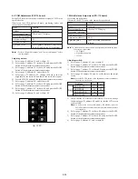
3-1-3. Adjusting Connectors
Some of the adjusting points of the video section are concentrated
at VC-217 board CN2904. Connect the measuring instruments via
the CPC-8 jig (J-6082-388-A). The following table lists the pin
numbers and signal names of CN2904.
Pin No.
1
3
5
7
9
11
13
15
17
19
Signal Name
LACN SIG
EVF BL–
EVF VCO
PD VG
H START
PANEL COM
TCK
TDO
SWP
GND
Pin No.
2
4
6
8
10
12
14
16
18
20
Signal Name
EVF BL+
EVF VG
GND
PD VCO
XHD/PSIG
TMS
TDI
GND
RF IN/LANC JACK IN
RF MON
Table 5-3-1.
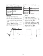
3-1-4. Connecting the Equipment
Connect the measuring instruments as shown in Fig. 5-3-2, and
perform the adjustments.
3-1-5. Checking the Input Signals
(Except AEP/UK model)
Because the video signal obtained from the pattern generator is used
as the adjustment signal for adjusting the VTR section, the video
output signal must satisfy the given specifications.
Connect the oscilloscope to the video terminal of the AUDIO/
VIDEO jack, and check that the sync signal amplitude of the video
signal is approximately <0.286V> [0.30V], the amplitude of the
video section is approximately <0.714> [0.70V], the amplitude of
the burst signal is approximately <0.286> [0.30V] and flat, and that
the level ratio of the burst signal to the “red” signal is 0.30 : 0.60.
The video signal used for adjusting the video section is shown in
Fig. 5-3-3.
< > : NTSC model
[ ] : PAL model
Fig. 5-3-2.
VTR recording mode (Except AEP/UK model)
Playback mode
Adjustment
remote
commander
LANC jack
Main unit
AUDIO/VIDEO jack
TV monitor
VIDEO
(Yellow)
AUDIO L (White)
AUDIO R (Red)
Main unit
LANC jack
AUDIO/VIDEO jack
Adjustment
remote
commander
VIDEO
(Yellow)
AUDIO L
(White)
AUDIO R
(Red)
Pattern generator
Video output
(75
Ω
)
CN2904
1
2
19
20
Remove the CPC cover
Fig. 5-3-1
Содержание Digital Handycam DCR-TRV10
Страница 10: ...1 2 ...
Страница 11: ...1 3 ...
Страница 12: ...1 4 ...
Страница 13: ...1 5 ...
Страница 14: ...1 6 ...
Страница 15: ...1 7 ...
Страница 16: ...1 8 ...
Страница 17: ...1 9 ...
Страница 18: ...1 10 ...
Страница 19: ...1 11 ...
Страница 20: ...1 12 ...
Страница 21: ...1 13 ...
Страница 22: ...1 14 ...
Страница 23: ...1 15 ...
Страница 24: ...1 16 ...
Страница 25: ...1 17 ...
Страница 26: ...1 18 ...
Страница 27: ...1 19 ...
Страница 28: ...1 20 ...
Страница 29: ...1 21 ...
Страница 30: ...1 22 ...
Страница 31: ...1 23 ...
Страница 32: ...1 24 ...
Страница 33: ...1 25 ...
Страница 34: ...1 26 ...
Страница 35: ...1 27 ...
Страница 36: ...1 28 ...
Страница 37: ...1 29 ...
Страница 38: ...1 30 ...
Страница 39: ...1 31 ...
Страница 40: ...1 32 ...
Страница 41: ...1 33 ...
Страница 42: ...1 34 ...
Страница 43: ...1 35 ...
Страница 44: ...1 36 ...
Страница 45: ...1 37E ...
Страница 56: ...DCR TRV8 TRV8E TRV10 TRV10E SECTION 3 BLOCK DIAGRAMS 3 1 3 2 3 3 3 4 3 1 OVERALL BLOCK DIAGRAM TRV8 TRV8E ...
Страница 57: ...DCR TRV8 TRV8E TRV10 TRV10E 3 5 3 6 3 7 3 8 3 2 OVERALL BLOCK DIAGRAM TRV10 TRV10E ...
Страница 58: ...DCR TRV8 TRV8E TRV10 TRV10E 3 3 POWER BLOCK DIAGRAM 3 9 3 10 3 11 3 12E ...
Страница 180: ... 264 OPTICAL AXIS FRAME Take a copy of OPTICAL AXIS FRAME with a clear sheet for use ...


