background image

6-14

DCR-SR32E/SR33E/SR42/SR42A/SR42E/SR52E/SR62/SR62E/SR72E/SR82/SR82C/SR82E_ADJ

1-5.

USB  SERIAL  No.  INPUT

The set is shipped with a unique ID (USB Serial No.) written in it.
This ID has not been written in a new board for service, and there-
fore it must be entered after the board replacement.
If original ID can be read from the board before replacement, read
it from the board before replacement using the “SERIAL READ/
WRITE” screen, and then write it after replacement.
If original ID cannot be read from the board before replacement,
write the ID for service using the “MANUAL WRITE” screen.
(The ID for service is different from the ID written when the set is
shipped.) Enter the PRODUCT ID (last 5 characters of model name)
and SERIAL No. into the screen and write them.

1.

Function of Each Button on USB Serial No. Input
Screen

Click the 

[USB SERIAL No. INPUT]

 button on the Main Menu screen,

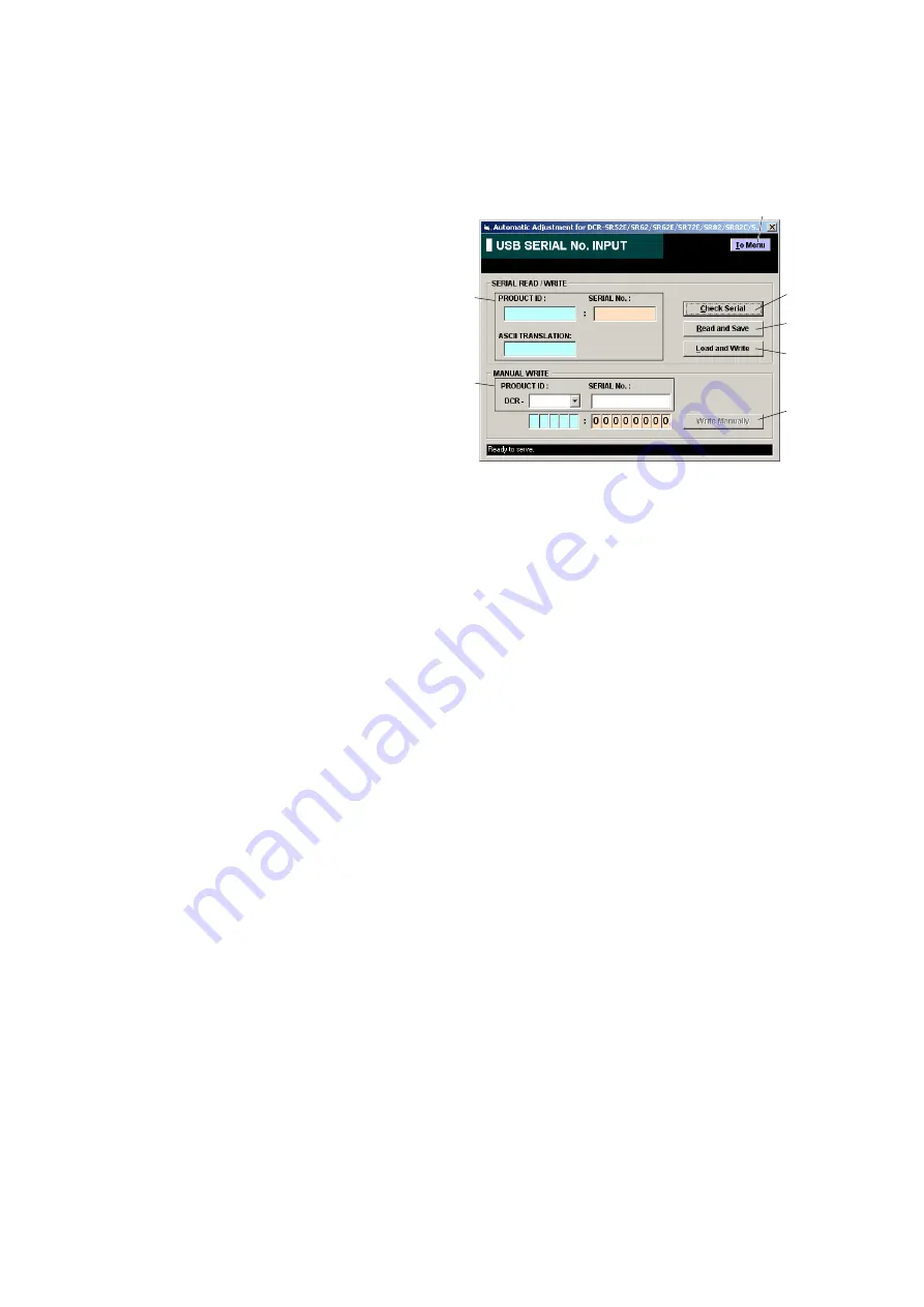
and the “USB SERIAL No. INPUT” screen in Fig. 6-1-8 will ap-
pear.

Fig. 6-1-8

1

[To Menu]

 button

The Main Menu screen comes back.

2

Display area
The “PRODUCT ID”, “SERIAL No.” and “ASCII TRANS-
LATION” are displayed.
For the “ASCII TRANSLATION”, the last 5 characters of
model name are displayed if the PRODUCT ID is set from the
model name in the MANUAL WRITE. For the PRODUCT ID
set in the factory, the model name is not displayed but “?” etc.
will be displayed.

3

[Check Serial]

 button

The USB SERIAL No. data is read from the camera and dis-
played in the display area.

4

[Read and Save]

 button

The USB SERIAL No. data is read from the camera and saved
in PC as a file.

5

[Load and Write]

 button

The USB SERIAL No. data is loaded from the file saved in
PC and written to the camera.

6

Input area
Enter “PRODUCT ID” and “SERIAL No.” when writing the
ID for service.
The “PRODUCT ID” is set from the last 5 characters of model
name if the model name is selected.
For the “SERIAL No.”, read it from the label on the camera
body and enter it.

7

[Write Manually]

 button

The USB SERIAL No. data entered in the input area is written
to the camera.

5

3

4

2

7

6

1

Содержание DCR-SR42

Страница 1: ...APPLICATION FOR ADJUSTMENT SeusEX SERVICE MODE DATA BACKUP SERVICE MODE Adjusting items when replacing main parts and boards Non MEGA model Adjusting items when replacing main parts and boards MEGA model Before starting adjustments List of Service tools DCR SR32E SR33E SR42 SR42A SR42E SR52E SR62 SR62E SR72E SR82 SR82C SR82E Use this Service Manual together with the Automatic Adjustment Program DC...

Страница 2: ...s 6 6 1 1 Preparations before Adjustments CAMERA Section 6 6 1 2 Adjustment Program 6 8 1 3 HDD System Adjustments 6 10 1 4 Destination Data Write 6 12 1 5 USB Serial No Input 6 14 1 6 Video System Adjustments 6 15 1 7 Camera System Adjustments Non MEGA model 6 18 1 8 Camera System Adjustments MEGA model 6 30 1 9 LCD System Adjustments 6 42 1 10 Error 6 45 6 2 Service Mode 6 47 2 1 Application for...

Страница 3: ... I O PD 317 board D6505 6507 LCD backlight PD 317 board IC6501 LCD driver Destination Data Set Destination data set USB Serial No Input USB serial No input Note 1 Origin oscillation check z S VIDEO OUT Y level adj S VIDEO OUT chroma level adj VIDEO OUT level check CAMERA adjustment 1 HALL adj z CAMERA adjustment 2 Flange back adj z z CAMERA adjustment 3 Flange back check z z CAMERA adjustment 4 Op...

Страница 4: ...ck z S VIDEO OUT Y level adj S VIDEO OUT chroma level adj VIDEO OUT level check CAMERA adjustment 1 HALL adj z CAMERA adjustment 2 Flange back adj z z CAMERA adjustment 3 Flange back check z z CAMERA adjustment 4 Optical axis adj z z F No standard data input MAX GAIN adj Color reproduction adj Color reproduction check AWB standard data input LV standard data input AWB adj AWB check LCD automatic a...

Страница 5: ...klight PD 318 board IC6501 LCD driver Destination Data Set Destination data set USB Serial No Input USB serial No input Note 1 Origin oscillation check z S VIDEO OUT Y level adj S VIDEO OUT chroma level adj VIDEO OUT level check CAMERA adjustment 1 HALL adj z CAMERA adjustment 2 Flange back and zoom lever center adj z z CAMERA adjustment 3 Flange back check z z F No standard data input MAX GAIN ad...

Страница 6: ... chroma level adj VIDEO OUT level check CAMERA adjustment 1 HALL adj z CAMERA adjustment 2 Flange back and zoom lever center adj z z CAMERA adjustment 3 Flange back check z z F No standard data input MAX GAIN adj Mechanical shutter adj Color reproduction adj Color reproduction check AWB standard data input LV standard data input AWB adj AWB check CAMERA adjustment 7 Steady shot check z z LCD autom...

Страница 7: ... each area how to get the application for adjustment SeusEX and HASP key J 2 USB cable 1 829 579 41 J 3 J 10 J 6 J 4 Pattern box PTB 450 J 6082 200 A or Small pattern box PTB 1450 J 6082 557 A J 7 Color bar chart For PTB 450 J 6020 250 A For PTB 1450 J 6082 559 A J 8 Clear chart For PTB 450 J 6080 621 A For PTB 1450 J 6082 560 A J 9 Minipattern box J 6082 353 B Siemens star chart J 6080 875 A Filt...

Страница 8: ... Adjustment Audio L HASP Key USB cable 1 829 579 41 AC adaptor AC L200 1 479 285 21 PC The SeusEX must be installed in the PC OS Windows 98 98SE Me 2000 XP RAM 256MB or more recommended USB 2 0 recommended also compatible with 1 1 Two connectors are required 6 1 CAMERA SECTION ADJUSTMENTS 1 1 PREPARATIONS BEFORE ADJUSTMENTS CAMERA SECTION 1 1 1 Preparations 1 Connect the equipment for adjustments ...

Страница 9: ...GITAL ZOOM MENU setting OFF 9 STEADY SHOT MENU setting OFF 10 DIGITAL EFFECT MENU setting OFF 11 PICTURE EFFECT MENU setting OFF 12 DEMO MODE MENU setting OFF Fig 6 1 4 3 Subjects 1 Color bar chart Color reproduction adjustment frame When performing adjustments using the color bar chart adjust the picture frame as shown in Fig 6 1 4 Color reproduction adjustment frame 2 Clear chart AWB adjustment ...

Страница 10: ...re sults such as EVR data to the set through two way communi cation with the camcorder via the SeusEX Accordingly the Automatic Adjustment Program must be used in the environ ment where the SeusEX operates 2 The Automatic Adjustment Program cannot be used when the SEUS or the SeusCam is running Exit the SEUS or the SeusCam before using the Automatic Adjustment Program 3 The SeusEX must be already ...

Страница 11: ... switch causes the Camcorder to be switched to the Adjustment Mode After the Camcorder restarted click the OK button in the message window 5 Upon successful completion of the settings in the Adjustment Mode the operation of each button on the Main Menu screen is enabled 7 Release of Adjustment Mode To finish the adjustment be sure to perform Release of Adjust ment Mode Releasing method 1 Click the...

Страница 12: ...ticAdjustment Program DCR SR42 Series Auto Adj Ver_1 r exe or DCR SR62 SeriesAuto Adj Ver_1 r exe is not used CheckHDDError vbe SetFactoryCheckDefault vbe SetFactoryCheckFull vbe ExecAfterFactoryCheck vbe For the VBScript files vbe the program is executed by double clicking the file Note The VBScript files can only be used on the PC in which the SeusEX is installed Ver 1 5 2007 09 ...

Страница 13: ...the connection Manegement file damaged Create new file will appear on the LCD screen of the camcorder and the select YES Execte the CheckHDDError vbe Double click the file Execte the SetFactoryCheckDefault vbe Double click the file Wait until JOB Success message is displayed several seconds Wait until JOB Success message is displayed several seconds Wait until JOB Success message is displayed seve...

Страница 14: ...ick the DESTINATION DATA WRITE button on the Main Menu screen and the DESTNATION DATA WRITE screen in Fig 6 1 7 will appear Fig 6 1 7 1 To Menu button The Main Menu screen comes back 2 Model Name List Selects the model name 3 Destination List Selects the written destination 4 Data Write button Write the destination data to the camcorder 2 Destination Data Write Writing method 1 Select the model na...

Страница 15: ...an Indonesia Melayu J1 J z U2 US z a a a a AR2 AR a a a z a E23 E z a a a a a a KR2 KR a a a a a z a JE3 JE z a a a a a a CA2 CND z a a a a a a E34 E z a a a a a a a a a a a a a a a a HK1 HK z a a a a a a a a a a a a a a a a AU2 AUS z a a a a a a a a a a a a a a a a CN2 CH a a a a a a a z a a a a a a a a a SV1 SV z a a a a a a a a a a a a a a a a JE3 JE z a a a a a a a a a a a a a a a a a a a a CE...

Страница 16: ...SERIAL No INPUT screen in Fig 6 1 8 will ap pear Fig 6 1 8 1 To Menu button The Main Menu screen comes back 2 Display area The PRODUCT ID SERIAL No and ASCII TRANS LATION are displayed For the ASCII TRANSLATION the last 5 characters of model name are displayed if the PRODUCT ID is set from the model name in the MANUAL WRITE For the PRODUCT ID set in the factory the model name is not displayed but ...

Страница 17: ...he adjustment completed successfully the data set ting is automatically cancelled and the button color returns to white 2 Adjustment Items of VIDEO System Adjustment The adjustment items of video system adjustment are as listed in Table 6 1 4 The Automatic Adjustment Program executes the ad justment items if the VIDEO Adjustment Start button is clicked Note The Automatic Adjustment Program does no...

Страница 18: ... 10 VC 489 board SIDE A IC2101 R2108 4 VIDEO Adjustment Automatic Adjustment Program execution items and sequence 1 Data Setting during Video Adj 2 S VIDEO OUT Y Level Adj 3 S VIDEO OUT Chroma Level Adj 4 VIDEO OUT Level Check 5 Release of Data Setting during Video Adj Adjusting method 1 Click the Start button of the VIDEO Adjustment 2 The Automatic Adjustment Program executes the 1 Data Setting d...

Страница 19: ... of the chroma signals satisfies the specified value and click the End button in the screen 5 If the End button is clicked 4 VIDEO OUT Level Check will be executed The following message and screen are dis played Check that the sync signal level and burst level of the video signals satisfies the specified value and click the OK button in the message 6 If the OK button is clicked 5 Release of Data S...

Страница 20: ... 3 Start button Each adjustment from Camera Adjustment 1 to Camera Adjustment 7 starts 4 Model Select radio button Selects the model to be adjusted Note NTSC model DCR SR42 SR42A PAL model DCR SR32E SR33E SR42E 5 Release Data Setting button The data setting at the adjustment is cancelled During the data setting the button color changes from white to red When the data setting is cancelled the butto...

Страница 21: ...ig Flange back adjustment chart and subject more than 500 m away CAMERA Adjustment 3 Flange Back Check Siemens star chart CAMERA Adjustment 4 Optical Axis Adj Clear chart 2 0 m from the front of lens 11 61 0E04 0E05 F No Standard Data Input 11 61 0260 to 026F MAX GAIN Adj 11 61 025E Color Reproduction Adj Color bar chart and Clear chart Color reproduction adjustment frame 11 61 0061 0063 0067 0068...

Страница 22: ...ring Camera Adj Adjusting method 1 Click the Start button of the CAMERA Adjustment 1 2 The AutomaticAdjustment Program executes 1 Data Setting during Camera Adj 3 If 1 Data Setting during Camera Adj completed success fully and the items 2 HALL Adj and 3 Release of Data Setting during Camera Adj will be executed 4 Upon successful completion of all items of the CAMERA Adjustment 1 the following mess...

Страница 23: ...utton is clicked 2 Flange Back Adj and 3 Release of Data Setting during CameraAdj will be executed 5 Upon successful completion of all items of the CAMERA Adjustment 2 the following message is displayed Click the OK button 4 CAMERA Adjustment 2 Using the minipattern box or flange back adjust ment jig Automatic Adjustment Program execution items and sequence 1 Data Setting during Camera Adj 2 Flang...

Страница 24: ...AMERA Adjustment 2 1 the following message is displayed Click the OK button 6 Perform CAMERA Adjustment 2 2 5 2 CAMERA Adjustment 2 2 Automatic Adjustment Program execution items and sequence 1 Data Setting during Camera Adj 2 Flange Back 2 Adj 3 Release of Data Setting during Camera Adj Preparation 1 Set the zoom lens to the TELE end and expose a subject that is more than 500 m away subjects with...

Страница 25: ...ng during Camera Adj 3 Upon successful completion of the 1 Data Setting during CameraAdj the following message is displayed Set the sub ject in accordance with the message 4 If the OK button is clicked 2 Flange Back Check is ex ecuted The following messages are displayed and then oper ate the camera to make a check in accordance with the mes sages 5 Upon completion of 2 Flange Back Check 3 Release...

Страница 26: ...of the 1 Data Setting during CameraAdj the following message is displayed Set the sub ject in accordance with the message 5 If the OK button is clicked 2 OpticalAxis Adj is executed The following messages are displayed and then operate the camera in accordance with the messages 6 After that the following screen is displayed Check on the monitor TV which area of optical axis deviation specification...

Страница 27: ...tomatic Adjustment Program executes 1 Data Setting during Camera Adj 4 Upon successful completion of the 1 Data Setting during Camera Adj the following message is displayed during the execution of 2 Picture Frame Setting Center Frame Set the subject in accordance with the message 5 If the OK button is clicked the following message is dis played and then check the size of clear chart shot on the mo...

Страница 28: ...heck on the oscilloscope 1 Horizontal period 2 Vertical period Check on the monitor TV Underscanned mode Fig 6 1 14 Adjusting method 1 Click the Start button in CAMERA Adjustment 6 and the following screen will appear 2 Select the model NTSC or PAL with the Model Select radio button Note NTSC model DCR SR42 SR42A PAL model DCR SR32E SR33E SR42E 3 Click the Color Reproduction Adjustment button 4 Th...

Страница 29: ...to the camcorder Upon successful completion the following message will be displayed Click the OK button and thus the adjustment is complete Checking method 1 Click the Start button in CAMERA Adjustment 6 and the following screen will appear 2 Select the model NTSC or PAL with the Model Select radio button Note NTSC model DCR SR42 SR42A PAL model DCR SR32E SR33E SR42E 3 Click the Color Reproduction...

Страница 30: ...Bit Value Discrimination bit Contents of Error 0 Blue NG 1 Red NG 2 Magenta NG 3 White NG 4 Green NG 5 Cyan NG 6 Yellow NG 7 Color bar Search NG Bit Value Discrimination The bit values must be discriminated from the data displayed on the SeusEX Whether bit values are 1 or 0 can be discrimi nated from the table shown below Data displayed on SeusEX 0 0 bit3 to bit0 discriminated bit7 to bit4 discrim...

Страница 31: ...ence 1 Data Setting during Camera Adj 2 Picture Frame Setting AWB Adjustment Frame 3 AWB Standard Data Input 4 LV Standard Data Input 5 AWB Adj 6 AWB Check 7 Release of Data Setting during Camera Adj Adjusting method 1 Select the model NTSC Model or PAL Model with the Model Select radio button Note NTSC model DCR SR42 SR42A PAL model DCR SR32E SR33E SR42E 2 Click the Start button of the CAMERA Adj...

Страница 32: ... button Each adjustment from Camera Adjustment 1 to Camera Adjustment 7 starts 4 Model Select radio button Selects the model to be adjusted Note NTSC model DCR SR62 SR82 SR82C PAL model DCR SR52E SR62E SR72E SR82E 5 Release Data Setting button The data setting at the adjustment is cancelled During the data setting the button color changes from white to red When the data setting is cancelled the bu...

Страница 33: ...stment jig Flange back adjustment chart and subject more than 500 m away CAMERA Adjustment 3 Flange Back Check Siemens star chart F No Standard Data Input 11 61 0260 to 026F MAX GAIN Adj 11 61 025E Mechanical Shutter Adj 11 61 0220 to 0235 Color Reproduction Adj Color bar chart and Clear chart Color reproduction adjustment frame Filter C14 for color temperature correction 11 61 0061 0063 0067 0068...

Страница 34: ...ring Camera Adj Adjusting method 1 Click the Start button of the CAMERA Adjustment 1 2 The AutomaticAdjustment Program executes 1 Data Setting during Camera Adj 3 If 1 Data Setting during Camera Adj completed success fully and the items 2 HALL Adj and 3 Release of Data Setting during Camera Adj will be executed 4 Upon successful completion of all items of the CAMERA Adjustment 1 the following mess...

Страница 35: ...utton is clicked 2 Flange Back Adj and 3 Release of Data Setting during CameraAdj will be executed 5 Upon successful completion of all items of the CAMERA Adjustment 2 the following message is displayed Click the OK button 4 CAMERA Adjustment 2 Using the minipattern box or flange back adjust ment jig Automatic Adjustment Program execution items and sequence 1 Data Setting during Camera Adj 2 Flang...

Страница 36: ...AMERA Adjustment 2 1 the following message is displayed Click the OK button 6 Perform CAMERA Adjustment 2 2 5 2 CAMERA Adjustment 2 2 Automatic Adjustment Program execution items and sequence 1 Data Setting during Camera Adj 2 Flange Back 2 Adj 3 Release of Data Setting during Camera Adj Preparation 1 Set the zoom lens to the TELE end and expose a subject that is more than 500 m away subjects with...

Страница 37: ...ng during Camera Adj 3 Upon successful completion of the 1 Data Setting during CameraAdj the following message is displayed Set the sub ject in accordance with the message 4 If the OK button is clicked 2 Flange Back Check is ex ecuted The following messages are displayed and then oper ate the camera to make a check in accordance with the mes sages 5 Upon completion of 2 Flange Back Check 3 Release...

Страница 38: ...CAMERA Adjustment 4 3 The AutomaticAdjustment Program executes 1 Data Setting during Camera Adj 4 Upon successful completion of the 1 Data Setting during Camera Adj the following message is displayed during the execution of 2 Picture Frame Setting Center Frame Set the subject in accordance with the message 5 If the OK button is clicked the following message is dis played and then check the size of...

Страница 39: ...scope 1 Horizontal period 2 Vertical period Check on the monitor TV Underscanned mode Fig 6 1 18 Adjusting method 1 Click the Start button in CAMERA Adjustment 5 and the following screen will appear 2 Select the model NTSC or PAL with the Model Select radio button Note NTSC model DCR SR62 SR82 SR82C PAL model DCR SR52E SR62E SR72E SR82E 3 Click the Color Reproduction Adjustment button 4 The follow...

Страница 40: ...hart with the color bar chart and with the C14 filter placed on the lens click the OK button 8 The data with the color bar chart C14 filter are captured the adjustment value is calculated and it is written to the camcorder Upon successful completion the following message will be displayed Click the OK button and thus the adjustment is complete Checking method 1 Click the Start button in CAMERA Adj...

Страница 41: ...Bit Value Discrimination bit Contents of Error 0 Blue NG 1 Red NG 2 Magenta NG 3 White NG 4 Green NG 5 Cyan NG 6 Yellow NG 7 Color bar Search NG Bit Value Discrimination The bit values must be discriminated from the data displayed on the SeusEX Whether bit values are 1 or 0 can be discrimi nated from the table shown below Data displayed on SeusEX 0 0 bit3 to bit0 discriminated bit7 to bit4 discrim...

Страница 42: ...n successful completion of the 1 Data Setting during Camera Adj the following message is displayed Then set the picture frame in accordance with the message 5 If the OK button is clicked 2 Picture Frame Setting AWB Adjustment Frame is executed The following messages are displayed in the order given below during the execution Then change the chart in accordance with the messages 6 After the setting...

Страница 43: ...era Adj 3 Upon successful completion of the 1 Data Setting during Camera Adj the following message is displayed With the camcoder in stationary state click the OK button 4 If the OK button is clicked 2 Steady Shot Check is ex ecuted Upon successful completion of the 2 Steady Shot Check the following message is displayed Check that the steadyshot function operates normally in accordance with the me...

Страница 44: ...r written from the SeusEX Note Button Name Adjustment LCD Adjustment Table 6 1 7 1 To Menu button The Main Menu screen comes back 2 Start button Each adjustment LCD Adjustment or Touch Panel Adjust ment starts 3 Release Data Setting button The data setting at the adjustment is cancelled During the data setting the button color changes from white to red When the data setting is cancelled the button...

Страница 45: ...on successful completion of all item the LCD Adjustment the following message is displayed Click the OK button 3 LCD Adjustment Automatic Adjustment Program execution items and sequence 1 Data Setting during LCD Adj 2 LCD Automatic Adj VCO Adj Contrast Adj 3 V COM Adj 4 Transmissive Mode White Balance Adj 5 Reflective Mode White Balance Adj MEGA model only 6 Release of Data Setting during LCD Adj ...

Страница 46: ...anel Adjustment 2 The Automatic Adjustment Program executes the 1 Touch Panel Adj 1 The following message is displayed and then adjust the LCD screen in accordance with the instructions given on the screen After the adjustment click the OK button in the message window 3 If the OK button is clicked 2 Release of Data Setting dur ing LCD Adj will be executed 4 Upon successful completion of all item t...

Страница 47: ...e and then re connect it tightly and check that the set is in USB Mode Install the power supply correctly Start the SeusEX and click the Connect to check that the connection state is established 2 RESET the CAMERA and Try Again Fig 6 1 21 Symptom The camera is not ready for adjustment Cause Data error exists in the camera Remedy Reset the camera 3 Adjustment Time Out Fig 6 1 22 Symptom Adjustment ...

Страница 48: ...tment may be left in the camera Note With this data left in the camera the camera will not oper ate normally In this case the Release Data Setting button is displayed in red on the screen as shown in Fig 6 1 24 to Fig 6 1 26 Click the Release Data Setting button to cancel the data setting When the data setting is cancelled the button color becomes white Video System Adjustment screen Fig 6 1 24 Ca...

Страница 49: ...ration Block change To change the block click Block on the SeusEX screen and enter the block to be changed The block is displayed in hexa decimal notation Page change To change the page click Page on the SeusEX screen and en ter the page to be changed The page is displayed in hexadeci mal notation Address change To change the address click Address on the SeusEX screen and enter the address to be c...

Страница 50: ...e switch was pressed its name characters change to blue in color 2 2 SERVICE MODE 1 Function of Each Button on Service Mode Screen Click the SERVICE MODE button on the Main Menu screen and the SERVICE MODE screen in Fig 6 2 2 will appear Fig 6 2 2 1 To Menu button The Main Menu screen comes back 2 Switch Check button SWITCH CHECK screen appears 3 LED Check button LED CHECK screen appears 4 Jack Ch...

Страница 51: ...JACK CHECK screen will appear Using method Click the Start button and the jack check will start During execution of jack check the connected jack is displayed in orange 3 LED Check Click the LED Check button on the SERVICE MODE screen and the LED CHECK screen will appear Using method LED ON or OFF can be controlled with LED ON or LED OFF button on the screen ...

Страница 52: ...d If the OK button is clicked and Camcorder is reset and it is re started and then the SERVICE MODE screen will come back 6 Record Data Click the Record Data button on the SERVICE MODE screen and the RECORD DATA screen will appear The record data such as use record and self diagnostic record are displayed Initializing method Self Diagnosis Data Only Click the Clear Self Diagnosis Data Only button ...

Страница 53: ...amera System Adjustments 3 LCD System Adjustments 1 Function of Each Button on Data Backup Screen Click the DATA BACKUP button on the Main Menu screen and the DATA BACKUP screen in Fig 6 2 3 will appear Fig 6 2 3 1 To Menu button The Main Menu screen comes back 2 Data Read and Save button Read the adjustment data from the camcorder and save them in PC as a file 3 Data Load and Write button Load th...

Страница 54: ...E SR52E SR62 SR62E SR72E SR82 SR82C SR82E_ADJ FOR CAMERA OPTICAL AXIS ADJUSTMENT Non MEGA model Take a copy of CAMERA OPTICAL AXIS FRAME with a clear sheet for use 0 180 90 67 5 22 5 337 5 292 5 247 5 202 5 157 5 112 5 8 4 5 7 1 6 2 3 270 ...

Страница 55: ...eplace the previously issued SERVICE MANUAL 9 852 190 51 with this Manual Change of Automatic Adjustment Program Correction of Description Mistake Change of G Sensor Check S M revised Page 6 8 Page 6 10 Page 6 50 Replace the SUPPLEMENT 1 SUPPLE MENT 2 SUPPLEMENT 3 and SUPPLE MENT 4 with the REVISED 1 Please discard the SUPPLEMENT 1 SUPPLE MENT 2 SUPPLEMENT 3 and SUPPLE MENT 4 Replace the previousl...

Страница 56: ... 7r07 Version of DCR SR62 Series Automatic Adjustment Program has been changed from Ver_1 6r05 into Ver_1 7r06 Correction of adjustment condition Change of the CAMERA SYSTEM ADJUSTMENTS Change of Color Reproduction Adj Check S M revised Page 2 Page 6 1 Page 6 2 Page 6 3 Page 6 4 Page 6 8 Page 6 18 Page 6 19 Page 6 21 Page 6 22 Page 6 23 Page 6 25 Page 6 26 Page 6 27 Page 6 28 Page 6 29 Page 6 30 P...

Отзывы: