DSC-U30
COVER
COVER
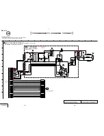
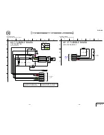
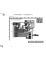
4-2. SCHEMATIC DIAGRAMS
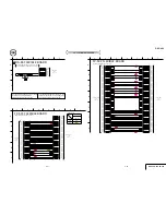
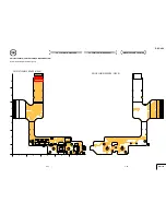
4-3. PRINTED WIRING BOARDS
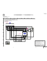
4-2. SCHEMATIC DIAGRAMS
4-3. PRINTED WIRING BOARDS
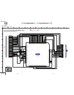
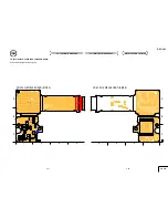
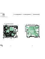
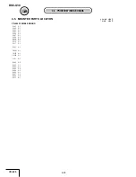
MOUNTED PARTS LOCATION
MOUNTED PARTS LOCATION
D050
D051
D052
FB050
LF050
LF051
LND058
R052
R053
R054
F005
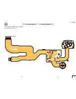
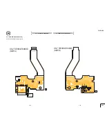
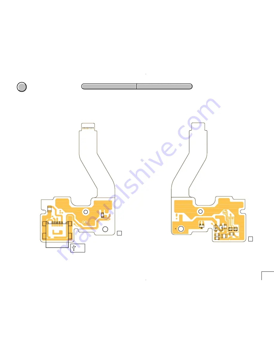
US-7 FLEXIBLE BOARD
(SIDE B)
1-687-286-
11
A
K
K
05
9
7
CN050
FB051
R051
LND050
LND051
LND052
LND053
LND054
LND055
LND056
LND057
1
5
6
8
US-7 FLEXIBLE BOARD
(SIDE A)
(USB)
1-687-286-
11
05
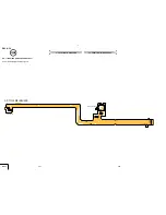
US-7 FLEXIBLE (USB CONNECTOR)
Note for Printed Wiring Board (See page 4-35).
4-50
US-7
4-49
Содержание Cyber-shot U DSC-U30
Страница 27: ...Schematic diagrams of the TY 20 PD 174 and DD 209 boards are not shown Pages from 4 11 to 4 24 are not shown ...
Страница 42: ...Waveforms of the TY 20 and PD 174 boards are not shown Pages 4 58 and 4 59 are not shown ...
Страница 44: ...Mounted parts location of the TY 20 PD 174 and DD 209 boards are not shown Pages 4 61 and 4 62 are not shown ...
Страница 57: ...DSC U30 76 Sony EMCS Co 2004J0500 1 2004 10 Published by DI Technical Support Section 9 876 263 31 ...

