DSC-U30
COVER
COVER
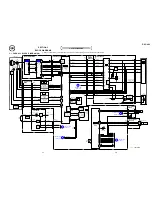
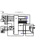
MA8082-(K8).S0
D051
330k
R053
100k
R052
R051
XX
R054
0
LND051
USB_5V
LND052
USB_5V
LND053
REG_GND (N.C.)
LND054
USB_D+
LND055
USB_D-
LND056
USB_GND
LND058
STATIC GND
LND057
USB_GND
LND050
USB_JACK_IN
D052
XX
MAZT082H08S0
D050
5P
CN050
1
VCC
2
D-
3
D+
4
ID
5
GND
FB050
FB051
XX
RB002
0
RB001
0
(USB)
CN907
TY-20 (4/4)
(PAGE 4-18)
1
8
D
E
3
1
2
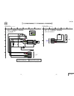
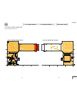
US-7 FLEXIBLE BOARD
4
C
B
6
05
A
5
XX MARK:NO MOUNT
USB CONNECTOR
PB
VIDEO
SIGNAL
SIGNAL PATH
Y/CHROMA
USB
USB
USB
USB
F005
(0.5A/50V)
4-28
For Schematic Diagram
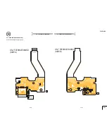
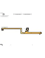
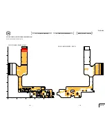
• Refer to page 4-49 for printed wiring board.
US-7, OP-17
4-27
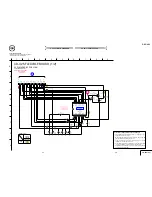
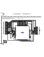
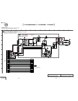
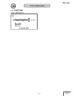
4-2. SCHEMATIC DIAGRAMS
US-7 FLEXIBLE BOARD OP-17 FLEXIBLE BOARD
4-2. SCHEMATIC DIAGRAMS
US-7 FLEXIBLE BOARD OP-17 FLEXIBLE BOARD
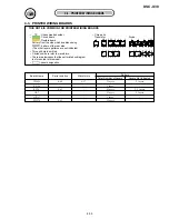
The components identified by mark
0
or dotted
line with mark
0
are critical for safety.
Replace only with part number specified.
Les composants identifiés par une marque
0
sont
critiques pour la sécurité.
Ne les remplacer que
par une piéce portant le numéro spécifié.
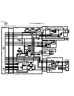
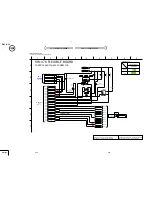
For Schematic Diagram
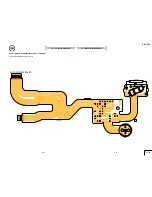
• Refer to page 4-51 for printed wiring board.
CN001
FLEXIBLE
(PAGE 4-29)
SW-376
680
R101
SML-310LTT86
D102
S101
1
2
LND101
LND102
LND103
LND104
LND106
LND105
MAZS051008SO
D101
(LENS COVER OPEN)
D_2.8V
GND
XLENS_CAP_OPEN
STATIC_GND
N.C.
XSELF_TIMER_LED
(SELF TIMER)
6
1
3
1
2
OP-17 FLEXIBLE BOARD
4
C
B
05
A
5
LENS COVER DETECT
Содержание Cyber-shot U DSC-U30
Страница 27: ...Schematic diagrams of the TY 20 PD 174 and DD 209 boards are not shown Pages from 4 11 to 4 24 are not shown ...
Страница 42: ...Waveforms of the TY 20 and PD 174 boards are not shown Pages 4 58 and 4 59 are not shown ...
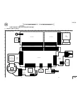
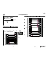
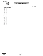
Страница 44: ...Mounted parts location of the TY 20 PD 174 and DD 209 boards are not shown Pages 4 61 and 4 62 are not shown ...
Страница 57: ...DSC U30 76 Sony EMCS Co 2004J0500 1 2004 10 Published by DI Technical Support Section 9 876 263 31 ...

