2-8
DSC-W35_L2
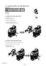
2-2-4. ADHERE THE ORNAMENTAL RING A
Apply an adhesive tape to two recesses on the top surface of the Barrier Assy.
Meeting a “notch” of the Ornamental Ring A with a “projection” of the group-1 frame, push the Ornamental Ring A into the group-1 frame.
*
The projection of the spring for preventing static electricity must be tilted.
Put the 60g weight on the Ornamental Ring A so that the Ornamental Ring A does not float up until the adhesive hardens.
Note:
Be careful not to give a shock.
*
After the weight was put, no gap must be present in full circumference between Ornamental Ring A and group-1 frame.
A gap, if present, causes the crackle sound NG.
*
The weight must push in the Ornamental Ring A only.
If the weight is put on the mold part of the Barrier Assy, the Ornamental Ring A will float up.
Completion after 30 minutes.
Adhesive
tape
Adhesive
tape
Do not put the weight on a black mold part.
Not gap in full circumference.
Содержание Cyber-shot DSC-W35
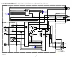
Страница 19: ...DSC W35_L2 Link Link 3 BLOCK DIAGRAMS OVERALL BLOCK DIAGRAM 2 2 OVERALL BLOCK DIAGRAM 1 2 POWER BLOCK DIAGRAM ...
Страница 27: ...DSC W35_L2 Schematic diagrams of the SY 175 board are not shown Pages from 4 6 to 4 11 are not shown ...
Страница 34: ...DSC W35_L2 Printed wiring boards of the SY 175 board are not shown Page 4 18 is not shown ...
Страница 38: ...DSC W35_L2 Mounted parts location of the SY 175 board are not shown Page 4 24 is not shown ...


