DSC-P9
5-42
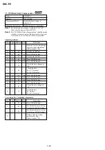
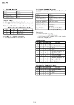
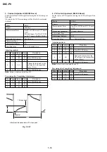
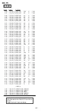
6. Switch Check (2)
Page 2
Addresses 91, 92, 94
Using method:
1) Select page: 2, addresses: 91, 92 and 94.
2) By discriminating the dispaly data, the pressed key can be
discriminated.
Address
Data
00 to 0C
0D to 27
28 to 48
49 to 73
74 to A5
A6 to DC
DD to FF
91
CONTROL DOWN
CONTROL UP
MENU
(KEY AD0)
(SELFTIMER)
(STROBO)
(SW-368 board)
(IC404
tg
)
(SW-368 board) (SW-368 board)
(S003)
(S004)
(S004)
92
CONTROL RIGHT CONTROL LEFT
CONTROL SET
DISPLAY/LCD
(KEY AD1)
(MACRO)
(REVIEW)
(SW-368 board)
ON/OFF
(IC404
th
)
(SW-368 board) (SW-368 board)
(S004)
(SW-368 board)
(S004)
(S004)
(S005)
94
ZOOM (W)
ZOOM (T)
(KEY AD3)
(SW-368 board) (SW-368 board)
(IC404
tk
)
(S001)
(S002)
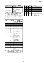
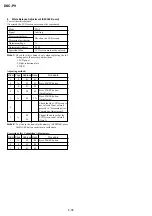
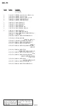
7. LED Check
Using method:
1)
Select page: 2, address: 04, set data: 02, and press the PAUSE
button of the adjusting remote commander.
2)
Check that all LED except for the ACCESS LED are lit and all
segments of LCD (display window) are lit.
3)
Select page: 2, address: 04, set data: 00 and press the PAUSE
button of the adjusting remote commander.
Page 2
Address 04
Data 02
Display Code
C:32:
ss
C:13:
ss
Countermeasure
Turn the power off and on again.
Format the “Memory stick”.
Insert a new “Memory Stick”.
Cause
Trouble with hardware.
Unformatted memory stick is inserted.
Memory stick is broken.
Caution Display During Error
SYSTEM ERROR
FORMAT ERROR
MEMORY STICK ERROR
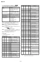
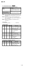
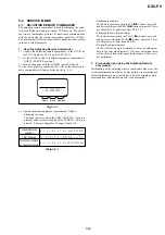
8. Self Diagnosis Code
E:61:
ss
E:91:
ss
Checking of lens drive circuit.
When failed in the focus and zoom
initialization.
Abnormality when flash is being
charged.
Checking of flash unit or replacement
of flash unit.
—
5-42 E

