29
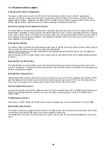
7.2.3 Operational Description
(1) IC102
This device provides the functions such as DSP1600 core, ADC, DAC, ROM, RAM, serial port, parallel host
interface, two timers, and error correction coprocessor (ECCP). This device is connected to the system controller,
RF, and Mic & Speaker to perform RF control and input/output of audio signals. As the operation clock, it uses
13MHz from the VCTCXO.
(2) IC101
This device provides the functions such as 32bit RISC processor, on-chip RAM, DMA, synchronous serial
interface, asynchronous serial interface, interrupt controller, SIM interface, timer, and ADC.
This device performs system control. As the operation clock, it uses 13MHz from the VCTCXO.
(3) IC103
A flash type ROM with the capacity of 32Mbits is used. The RAM capacity is 4Mbits. The data bus width is 16 bits
or 8 bits. Here, the programs and telephone directory data are stored.
(4) IC104
This device provides the functions such as key scanning, interrupt extension, power supply circuit control, watch
dog timer, voltage monitoring, and output port extension. It is connected to the system controller (IC101) data
bus.
(5) IC203
This device provides the audio signal recording and playing function and also the audio path switching function. It
is capable of recording for 4 minutes at 8kHz sampling. It is subject to synchronous serial control by the system
controller (IC101).
(6) IC301
This device is a system power supply with the built-in three regulators, two voltage detectors, one vibrator driver,
and three FETs.
(7) IC201
This device is a real time clock. It is subject to synchronous serial control by the system controller (IC101). This
real time clock outputs 32kHz clock, and supplies it to the IC101, IC102 and IC104.
(8) LCD1 (LCD Module)
The specifications of this liquid crystal display are as follows.
Glass size: 38mm x 31.5mm
Number of dots: 96x72 dots
LCD driver: HD66728
The LCD is connected to the system controller (IC101) data bus.
Содержание CMD-MZ5
Страница 12: ...12 4 2 The Basic Features of the CMD MZ5 ...
Страница 13: ...13 ...
Страница 14: ...14 4 3 Icon Glossary ...
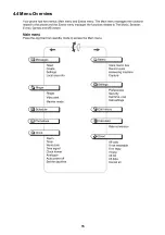
Страница 15: ...15 4 4 Menu Overview ...
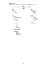
Страница 16: ...16 ...
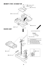
Страница 18: ...18 MEMORY STICK CONNECTOR BOARD ASSY ...
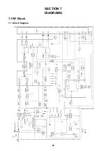
Страница 24: ...24 SECTION 7 DIAGRAMS 7 1 RF Block 7 1 1 Block Diagram ...
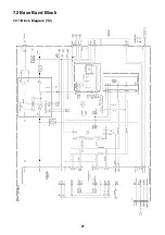
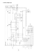
Страница 27: ...27 7 2 Base Band Block 7 2 1 Block Diagram 1 2 ...
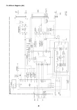
Страница 28: ...28 7 2 2 Block Diagram 2 2 ...
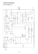
Страница 30: ...30 7 3 Memory Stick Block 7 3 1 Block Diagram 1 2 ...
Страница 31: ...31 7 3 2 Block Diagram 2 2 ...
Страница 35: ...Sony Corporation Digital Telecommunication Company 9 870 403 01 2001 5 Published by After Sales Service ...

