background image

SERVICE MANUAL

Sony Corporation

eVehicle Division
Published by Sony Techno Create Corporation

US Model

Canadian Model

AEP Model

UK Model

E Model

9-887-472-02

2007D04-1
© 2007.04

Ver. 1.1  2007.04

SPECIFICATIONS

CDX-HR70MW/HR70MS:
FM

Tuning range

87.5 – 108.0 MHz

Antenna (aerial) terminal External antenna (aerial) connector
Intermediate frequency

10.7 MHz/450 kHz

Usable sensitivity

9 dBf

Selectivity

75 dB at 400 kHz

Signal-to-noise ratio

67 dB (stereo), 69 dB (mono)

Harmonic distortion at 1 kHz

0.5 % (stereo), 0.3 % (mono)

Separation

35 dB at 1 kHz

Frequency response

30 – 15,000 Hz

MW/LW

Tuning range

MW: 531 – 1,602 kHz
LW: 153 – 279 kHz

Antenna (aerial) terminal External antenna (aerial) connector
Intermediate frequency

10.7 MHz/450 kHz

Sensitivity

MW: 30 

µ

V, LW: 40 

µ

V

• The tuner and CD sections have no adjustments.

– Continued on next page –

CDX-HR70MS/HR70MW/

HS70MS/HS70MW

AUDIO POWER SPECIFICATIONS

POWER OUTPUT AND TOTAL HARMONIC DISTORTION
23.2 watts per channel minimum continuous average power into
4 ohms, 4 channels driven from 20 Hz to 20 kHz with no more
than 5% total harmonic distortion.

Model Name Using Similar Mechanism

CDX-GT51W/GT510/
GT560/GT560S

CD Drive Mechanism Type

MG-101FA-188//Q

Optical Pick-up Name

DAX-25A

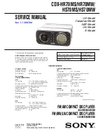
FM/AM COMPACT DISC PLAYER

CDX-HS70MS/HS70MW

FM/MW/LW COMPACT DISC PLAYER

CDX-HR70MS/HR70MW

CD player section

Signal-to-noise ratio

120 dB

Frequency response

10 – 20,000 Hz

Wow and flutter

Below measurable limit

Tuner section
CDX-HS70MW/HS70MS:
FM

Tuning range

87.5 – 108.0 MHz (at 50 kHz step)
87.5 – 107.9 MHz (at 200 kHz step)

FM tuning interval

50 kHz/200 kHz switchable

Antenna (aerial) terminal External antenna (aerial) connector
Intermediate frequency

10.7 MHz/450 kHz

Usable sensitivity

9 dBf

Selectivity

75 dB at 400 kHz

Signal-to-noise ratio

67 dB (stereo), 69 dB (mono)

Harmonic distortion at 1 kHz

0.5 % (stereo), 0.3 % (mono)

Separation

35 dB at 1 kHz

Frequency response

30 – 15,000 Hz

AM

Tuning range

531 – 1,602 kHz (at 9 kHz step)
530 – 1,710 kHz (at 10 kHz step)

AM tuning interval

 9 kHz/10 kHz switchable

Antenna (aerial) terminal External antenna (aerial) connector
Intermediate frequency

10.7 MHz/450 kHz

Sensitivity

30 

µ

V

Содержание CDX-HS70MW - Marine Stereo

Страница 1: ...nuous average power into 4 ohms 4 channels driven from 20 Hz to 20 kHz with no more than 5 total harmonic distortion Model Name Using Similar Mechanism CDX GT51W GT510 GT560 GT560S CD Drive Mechanism Type MG 101FA 188 Q Optical Pick up Name DAX 25A FM AM COMPACT DISC PLAYER CDX HS70MS HS70MW FM MW LW COMPACT DISC PLAYER CDX HR70MS HR70MW CD player section Signal to noise ratio 120 dB Frequency res...

Страница 2: ...nal BUS control input terminal BUS audio input terminal Remote controller input terminal Antenna aerial input terminal AUX input terminal Tone controls Low 10 dB at 60 Hz XPLOD Mid 10 dB at 1 kHz XPLOD High 10 dB at 10 kHz XPLOD Power requirements 12 V DC boat battery negative ground earth Dimensions Approx 197 89 187 mm 7 7 8 3 5 8 7 3 8 in w h d Mounting dimensions Approx 181 52 144 mm 7 1 4 2 1...

Страница 3: ...ck You can play CD DA also containing CD TEXT and CD R CD RW MP3 WMA AAC files also containing Multi Session and ATRAC CD ATRAC3 and ATRAC3plus format Type of discs Label on the disc CD DA MP3 WMA AAC ATRAC CD A CD TEXT disc is a CD DA that includes information such as disc artist and track name TABLE OF CONTENTS 1 SERVICE NOTE 4 2 GENERAL Location of Controls 5 Connection Example CDX HS70MS HS70M...

Страница 4: ...ver be disassembled since it is waterproof finished Replace the front panel overall assembly completely when replacing the key board or other components of the front panel EXTENSION CABLE AND SERVICE POSITION When repairing or servicing this set connect the jig extension cable as shown below Connect the MAIN board CNP350 and the SERVO board CN2 with the extension cable Part No J 2502 076 1 SECTION...

Страница 5: ... again within about 1 second and hold reverse fast forward a track press and hold Radio To tune in stations automatically press find a station manually press and hold M SELECT button To select setup items N SOURCE button To power on change the source Radio CD MD 1 AUX O Frequency select switch CDX HS70MW HS70MS located on the bottom of the unit See Frequency select switch in the supplied installat...

Страница 6: ...ikt Tip 2 B Om twee of meer CD MD wisselaars aan te sluiten hebt u de geluidsbronkiezer XA C40 niet bijgeleverd nodig CONNECTION EXAMPLE CDX HR70MS HR70MW A B AUDIO OUT REAR AUDIO OUT FRONT BUS AUDIO IN BUS CONTROL IN REMOTE IN AUDIO OUT REAR SUB BUS AUDIO IN BUS CONTROL IN not supplied non fourni no suministrado nicht mitgeliefert niet bijgeleverd non in dotazione Source selector Sélecteur de sou...

Страница 7: ...iquement aux amplificateurs Le raccordement de tout autre système risque d endommager l appareil 4 Vers le câble d interface d un téléphone 5 Vers le signal d éclairage Commencez par raccorder le câble de mise à la masse noir à un point métallique du bateau 6 Vers la borne 12 V qui est alimentée quand la clé de contact est sur la position accessoires Remarque S il n y a pas de position accessoires...

Страница 8: ... danneggiare l apparecchio Onde evitare problemi di funzionamento non utilizzare i cavi dei diffusori incorporati installati nell imbarcazione se l apparecchio condivide un cavo comune negativo per i diffusori destro e sinistro Non collegare fra loro i cavi dei diffusori dell apparecchio Nota sui collegamenti Se l amplificatore e il diffusore non sono collegati correttamente FAILURE viene visualiz...

Страница 9: ... BOARD Page 11 1 CHUCKING ARM SUB ASSY SUPPLEMENT 1 Page 1 2 SLED MOTOR ASSY SUPPLEMENT 1 Page 2 3 OPTICAL PICK UP SECTION SUPPLEMENT 1 Page 3 4 OPTICAL PICK UP SUPPLEMENT 1 Page 3 SECTION 3 DISASSEMBLY Note This set can be disassemble according to the following sequence 3 1 FRONT PANEL OVERALL ASSY 4 three tapping screws P2 5 three tapping screws P2 1 cover connector 2 panel cover FPC 3 flexible ...

Страница 10: ...umerical order given 3 2 SUB PANEL SECTION 2 two screws P 2 6 6 S TITE 1 seal base 3 two screws K 5 8 4 two screws K 5 8 CN701 CN802 6 sub panel section 5 7 CN350 6 4 screw PTT 2 6 6 2 screw PTT 2 6 6 S TITE 3 cover 1 sheet chassis 5 screw PTT 2 6 6 8 two screws PTT 2 6 4 9 bracket CD 0 CD mechanism block ...

Страница 11: ... PTT 2 6 6 0 two screws P 2 6 10 qa screw PTT 2 6 10 qs heat sink 6 cord RCA 8 two screws P 2 6 8 9 two screws PTT 2 6 12 7 screw PTT 2 6 10 4 CN410 3P 5 SERVO board SERVO board claw claw 3 toothed lock screw M 1 7 2 5 2 toothed lock screw M 1 7 2 5 1 Remove the eleven solders GRY YEL BLU ORG RED BLK RED WHT BLK RED WHT 4 optical pick up 16 core CN1 ...

Страница 12: ...0MW HS70MS HS70MW 3 7 ROLLER ARM ASSY 3 6 CHASSIS T SUB ASSY 4 chassis T sub assy 3 claw 1 two precision screws P 1 7 2 2 2 two precision screws P 1 7 2 2 3 washer 4 gear RA1 5 roller arm assy 1 spring RAL 2 spring RAR ...

Страница 13: ...13 CDX HR70MS HR70MW HS70MS HS70MW 3 8 CHASSIS OP ASSY 7 coil spring damper natural 8 coil spring damper green 6 chassis OP assy 5 1 tension spring KF 2 gear LE1 3 lever D 4 slider R Ver 1 1 ...

Страница 14: ... 1 GP ALBM keys during the number of connected units display mode 4 4 Operating hours display mode Reset count display OFFSET FAILURE error display CD error information display Operating hours display Number of connected units display Reset count by watchdog timer display 0 1 X X 0 2 X X 0 3 1 X X X 0 4 X X X X 0 5 1 X X 0 6 1 X X X X X Reset count in hexadecimal format Diag code 01 Reset count 0 ...

Страница 15: ...details display CD error info history 3 Disc type plus operating hours display CD error info history 3 Error description plus error details display CD error info history 2 Disc type plus operating hours display CD error info history 2 Error description plus error details display CD error info history 1 latest Disc type plus operating hours display 0 5 1 X X X X X 0 5 2 X X 0 5 2 X X X X X 0 5 3 X ...

Страница 16: ...16 CDX HR70MS HR70MW HS70MS HS70MW MEMO ...

Страница 17: ...TT D_3 3V A_3 3V BU_3 3V DR_6V MECHA6V 3 3V SERVO3 3V UNISI UNISO UNISCK SYSRST LINK_OFF BUSON BUIN R CH D511 D400 D493 D491 11 VDD5V 15 E2PVDD AU8V TU 5V 3 3V L 3 R 14 SDA 13 SCL 7 TUN_MUTE 6 S METER 17 E2PSDA 5 QUALITY 11 1 9 2 4 12 3 11 5 6 16 14 13 7 15 10 15 21 22 24 26 16 5 7 28 27 25 9 18 19 8 1 2 6 16 E2PSCL R R L L J451 1 2 BUS AUDIO IN J1 ANTENNA CNP350 S103 RESET AUX IN TU1 TUNER UNIT E...

Страница 18: ...te X parts extracted from the component side Y parts extracted from the conductor side a Through hole Pattern from the side which enables seeing The other layers patterns are not indicated A B Line B B Line H adjustment for repair Voltages and waveforms are dc with respect to ground under no signal detuned conditions no mark TUNER CD PLAY Impossible to measure Voltages are taken with a VOM Input i...

Страница 19: ...C605 L400 L401 L5 JC420 Q589 D117 C115 R599 D599 JC599 FB301 C426 C446 C999 TU1 S501 CN410 X50 C1 C61 CN701 D607 C321 C485 C600 C503 J370 REMOTE IN CNJ400 BUS CONTROL IN C306 C308 C303 X500 R710 C314 JW77 D306 C310 D311 D309 C311 D302 D301 R705 C403 J451 C491 C505 D304 JW76 D303 C701 C300 CNJ400 JW74 J1 ANTENNA D307 C317 C363 D308 C501 CN350 D305 C316 D312 D310 C364 TH400 C401 X501 L300 C703 C480 ...

Страница 20: ... C466 C318 C319 JC504 JC300 JC301 C301 C304 C324 C305 JC302 C309 C307 C502 C325 JC999 D310 D311 D312 D309 D308 D307 D306 D305 D303 D304 JC601 C323 C303 CN300 R706 R611 JC600 R602 R601 C601 FB301 IC601 J370 CNJ400 L300 FU601 D701 D702 D703 D903 D607 Q701 Q703 Q702 D705 D704 D602 Q605 D603 Q601 D604 D605 D606 D491 Q491 Q492 IC502 IC300 R710 R701 R709 R705 L301 L303 L302 C316 C315 C314 C313 C310 C320...

Страница 21: ...414 JC998 C14 FB131 C481 C50 C60 C54 C55 C49 JC32 C9 JC3 C3 C302 C326 JC1 C62 C58 C63 C57 C56 R3 R2 R1 C8 R6 R7 L1 R13 R12 C7 R4 R5 C12 C13 R8 R9 C434 JC400 R361 Q440 Q420 Q450 Q430 JC420 Q460 Q470 C454 L401 C461 C471 JC522 JC7 R52 C64 JC9 C5 L400 IC401 C487 R483 R481 J1 Q1 Q3 J451 TU1 Q50 C61 IC50 C1 C4 D2 R11 L3 L2 C51 C52 C53 C365 C366 C363 C364 R482 C330 C331 C483 C482 C328 C327 R480 C367 C480...

Страница 22: ... R597 R596 JC105 CN701 C405 JW599 D599 R535 R407 FB408 R518 R517 R522 R555 R556 C403 R400 C410 R536 JC350 R516 JC518 R570 JC505 R554 JC502 IC602 D502 R529 R550 JC90 JC511 R541 JC524 JC512 JC515 CN350 R547 R370 R527 S103 L500 X500 R574 JC506 IC501 C508 Q501 D501 R538 Q591 R599 Q590 Q589 FB407 FB406 FB405 D113 D103 R530 R531 R532 R533 R534 R546 C505 C506 R507 R508 R503 R502 R501 R505 R511 R544 C109 ...

Страница 23: ...S HS70MW 1 A B C D E F G H I 2 3 4 5 6 7 8 9 10 FMA3 17 1 LED801 DISC SLOT LSW801 LSW801 CN802 PANEL OPEN DETECT 11 11 1 871 923 11 11 1 871 923 MAIN BOARD CN701 A S802 FRONT PANEL UNIT FMA4 CN801 5 7 PRINTED WIRING BOARD SUB SECTION Uses unleaded solder Page 19 ...

Страница 24: ...24 24 CDX HR70MS HR70MW HS70MS HS70MW CDX HR70MS HR70MW HS70MS HS70MW LED801 LSW801 2 2 LSW801 1 2 S802 CN801 CN802 5 8 SCHEMATIC DIAGRAM SUB SECTION Page 22 ...

Страница 25: ... REGULATOR 1 3 5 7 9 11 13 15 17 19 21 23 25 27 29 31 33 35 37 2 4 6 8 10 12 14 16 18 20 22 24 26 28 30 32 34 36 TAB LF LF LR LR IN_RL SGND IN_LF RR RR RF RF DIAG SW2 SW1 REG3 REG4 VP REG2 SDA SCL VP2 PGND3 SVR IN_RR IN_LR ACGND PGND2 VP1 STB PGND1 RST CRES REG1 GND REG5 CBU FL RL RR VP FR I 2 C BUS IC601 BA8271F E2 MAIN Board 1 3 1 2 3 4 5 6 7 8 9 10 14 13 12 11 BUS ON SWITCH RESET SWITCH BATTERY...

Страница 26: ...BASS MIDDLE SPECTRUM ANALYZER FADER 25 OUTFL 24 OUTRR 23 OUTRL FADER FADER 22 OUTSR 21 20 OUTSL 19 ADJ 18 SOUT 17 DATA CLK FADER FADER LPF EFFECT INPUT GAIN FADER VDDA INTERPOLATOR RAM BUFFER CONTROL LOGIC TEST LOGIC PIN MUX S I 2 C SPI INTERFACE BAND PASS FILTER SIGMA DELTA CONVERTER SINC4 FILTER REF3 REF2 REF1 VSS VDDD RESETN TM 1 MPX 16 CSN SDAOUT RDSREG 3 INTN MPX SINC4REG SDAIN SCK SPI TESTRE...

Страница 27: ...CD driver chip enable signal output 28 LCD_SO FLS_SO O LCD driver serial data signal output 29 LCD_SCK O LCD driver serial clock signal output 30 RDSON O RDS ON signal output 31 NCO O Not used Open 32 SA_DATA O Spectrum analyzer data signal output 33 I2C_CKO O I2C bus serial clock signal output 34 I2C_SIO I O I2C bus serial data signal input output 35 DAVDD A D converter power supply 3 3V 36 AVRH ...

Страница 28: ... OFF 76 XKEYON O Key acknowledgment enable signal output 77 RESET I System reset signal input 78 NCO O Not used Open 79 XOUT O Sub clock signal output 32 768kHz 80 XIN I Sub clock signal input 32 768kHz 81 VSS1 Ground 82 OSCIN I Main clock signal input 18 432kHz 83 OSCOUT O Main clock signal output 18 432kHz 84 VCC3 Power supply 3 3 V 85 NCO O Not used Open 86 ATT O Audio mute control signal outpu...

Страница 29: ...reference number in the exploded views are not supplied Items marked are not stocked since they are seldom required for routine service Some delay should be anticipated when ordering these items XX and X mean standardized parts so they may have some difference from the original one Color Indication of Appearance Parts Example KNOB BALANCE WHITE RED Parts Color Cabinet s Color Accessories are given...

Страница 30: ...095 11 PRINTED WIRING BOARD FLEXIBLE 62 3 081 999 11 SCREW B1 7 TAPPING 63 2 696 237 01 HOLDER SWITCH 64 2 698 288 01 SPRING SWITCH 65 2 696 236 01 LEVER SWITCH 66 3 040 990 11 BUTTON EJECT HR70MW HS70MW 66 3 040 990 21 BUTTON EJECT HR70MS HS70MS 67 A 1216 150 A PANEL OVERALL ASSY SUB HR70MW HS70MW 67 A 1224 918 A PANEL OVERALL ASSY SUB HR70MS HS70MS 68 2 889 258 11 SCREW B M2 EG GRIP Ref No Part ...

Страница 31: ...4 798 01 CAP FU601 1 532 877 11 FUSE BLADE TYPE AUTO FUSE 10A TU1 A 3220 961 B TUNER UNIT TUX 032 1 7 685 792 09 SCREW PTT 2 6X6 S 2 7 685 790 01 SCREW PTT 2 6X4 S 3 7 685 793 09 SCREW PTT 2 6X8 S 4 7 685 794 09 SCREW PTT 2 6X10 S 5 7 685 134 19 SCREW P 2 6X8 TYPE2 NON SLIT 6 7 685 795 09 SCREW PTT 2 6X12 S 7 7 621 284 40 SCREW P 2 6X10 Ref No Part No Description Remark Ref No Part No Description ...

Страница 32: ...69 01 SCREW M2X3 SERRATION 155 3 348 998 31 SCREW M1 4X2 5 TAPPING PAN 156 3 352 758 31 SCREW M1 7X2 5 TOOTHED LOCK 157 A 1177 362 A SERVO BOARD COMPLETE 8 7 627 000 08 SCREW PRECISION P 1 7X2 2 TYPE3 Ref No Part No Description Remark Ref No Part No Description Remark not supplied 8 8 not supplied not supplied not supplied not supplied not supplied not supplied not supplied not supplied not suppli...

Страница 33: ... 25V C302 1 127 715 11 CERAMIC CHIP 0 22uF 10 16V C303 1 128 551 11 ELECT 22uF 20 63V C304 1 115 340 11 CERAMIC CHIP 0 22uF 10 25V C305 1 162 970 11 CERAMIC CHIP 0 01uF 10 25V C306 1 126 964 11 ELECT 10uF 20 50V C307 1 162 970 11 CERAMIC CHIP 0 01uF 10 25V C308 1 126 964 11 ELECT 10uF 20 50V C309 1 115 340 11 CERAMIC CHIP 0 22uF 10 25V C310 1 126 916 11 ELECT 1000uF 20 6 3V C311 1 124 589 11 ELECT...

Страница 34: ...uF 10 50V HR70MS HR70MW C509 1 162 970 11 CERAMIC CHIP 0 01uF 10 25V C510 1 162 964 11 CERAMIC CHIP 0 001uF 10 50V C511 1 162 964 11 CERAMIC CHIP 0 001uF 10 50V C512 1 162 964 11 CERAMIC CHIP 0 001uF 10 50V C513 1 162 964 11 CERAMIC CHIP 0 001uF 10 50V C515 1 162 917 11 CERAMIC CHIP 15PF 5 50V C516 1 162 918 11 CERAMIC CHIP 18PF 5 50V C519 1 162 970 11 CERAMIC CHIP 0 01uF 10 25V C523 1 162 927 11 ...

Страница 35: ...1 SHORT CHIP 0 JC491 1 216 296 11 SHORT CHIP 0 JC501 1 216 296 11 SHORT CHIP 0 JC502 1 216 296 11 SHORT CHIP 0 JC503 1 216 296 11 SHORT CHIP 0 JC504 1 216 296 11 SHORT CHIP 0 JC505 1 216 296 11 SHORT CHIP 0 JC506 1 216 864 11 SHORT CHIP 0 HR70MS HR70MW JC508 1 216 296 11 SHORT CHIP 0 JC511 1 216 864 11 SHORT CHIP 0 JC512 1 216 864 11 SHORT CHIP 0 JC515 1 216 864 11 SHORT CHIP 0 JC518 1 216 296 11 ...

Страница 36: ...09 11 METAL CHIP 100 5 1 10W R441 1 216 809 11 METAL CHIP 100 5 1 10W R442 1 216 833 11 METAL CHIP 10K 5 1 10W R450 1 216 809 11 METAL CHIP 100 5 1 10W R451 1 216 809 11 METAL CHIP 100 5 1 10W R452 1 216 833 11 METAL CHIP 10K 5 1 10W R453 1 216 864 11 SHORT CHIP 0 R454 1 216 864 11 SHORT CHIP 0 R455 1 216 825 11 METAL CHIP 2 2K 5 1 10W R460 1 216 809 11 METAL CHIP 100 5 1 10W R461 1 216 809 11 MET...

Страница 37: ... 1 10W R703 1 216 833 11 METAL CHIP 10K 5 1 10W R704 1 216 833 11 METAL CHIP 10K 5 1 10W R705 1 249 425 11 CARBON 4 7K 5 1 4W R706 1 216 841 11 METAL CHIP 47K 5 1 10W R707 1 216 841 11 METAL CHIP 47K 5 1 10W R708 1 216 829 11 METAL CHIP 4 7K 5 1 10W R709 1 216 821 11 METAL CHIP 1K 5 1 10W R710 1 249 425 11 CARBON 4 7K 5 1 4W R711 1 216 845 11 METAL CHIP 100K 5 1 10W R712 1 216 837 11 METAL CHIP 22...

Страница 38: ...MS HR70MW 203 1 833 102 11 CORD WITH CONNECTOR POWER HS70MW HS70MS 204 2 898 494 01 SHEET INSTALLATION 205 not supplied 206 X 2149 840 1 SCREW ASSY MARINE 207 2 338 744 01 NUT SPEED U TYPE 208 not supplied 209 X 3382 926 1 SCREW ASSY BS FITTING 210 3 349 410 11 BUSHING Ref No Part No Description Remark 201 202 204 205 208 209 6 2 M3 35 6 M3 40 2 2 M3 NUT 2 203 210 206 207 ...

Страница 39: ... removal of the OPTICAL PICK UP added DISASSEMBLY 1 CHUCKING ARM SUB ASSY 3 chucking arm sub assy 2 1 spring Note Have this portion receive the chassis Note Have this portion receive the chassis Note Be careful not to touch the turn table US Model Canadian Model AEP Model UK Model E Model CDX HR70MS HR70MW HS70MS HS70MW ...

Страница 40: ...d stand turn table 2 three serration screws M 2 3 three serration screws M 2 3 Note Place the stand with care not to touch the turn table Note Never remove these parts since they were adjusted Note for Assembly Note Take care to prevent the chassis from being bent when tightening the three machine screws ...

Страница 41: ... section There is space at the end of the leaf spring sub guide to avoid contact with the slide 1 pan tapping screw M 1 4 2 5 2 leaf spring sub guide 3 leaf spring OP 5 optical pick up 4 lead screw assy Notes for Assembly Prevent the end of the leaf spring sub guide from being in contact with the OP slide base Prevent the end of the leaf spring sub guide from being in contact with the OP slide bas...

Страница 42: ... allows you to jump to the revised page Also clicking the version at the upper on the revised page allows you to jump to the next revised page Ver Date Description of Revision 1 0 2006 11 New 1 1 2007 04 Notes for removal of the OPTICAL PICK UP added SUPPLEMENT 1 ENG 07003 ...

Отзывы: