background image

22

Menu Operations

To cancel a changed setting

Set the STATUS/CANCEL switch to CANCEL before 
pushing the menu control knob to restore the original 
setting.

To suspend menu changes

Set the DISPLAY/MENU switch to OFF to turn off the 
menu screen display.
The menu setting operation can be restarted by setting 
the DISPLAY/MENU switch back to MENU.

3

Push the menu control knob.

The 

?

 (question mark) changes back to 

,

, and the item 

setting is registered.

4

To change other settings on the same menu page, 
repeat steps 1 to 3.

To enter a character string

If you press the menu control knob when the 

,

 cursor is 

pointing to a text item, such as a file ID, a square cursor and 
the list of selectable characters are displayed.
The cursor is moved by turning the menu control knob.

1

Move the cursor to the position where you wish enter 
a character and push the menu control knob.

The cursor is displayed in the character list.

2

Move the cursor to the character to enter and push 
the menu control knob.

Repeat steps 

1

 and 

2

 to enter other characters.

• Select INS to insert a space character at the cursor 

position.

• Select DEL to delete the character at the cursor 

position.

• Select RET to return to step 

1

 without changing the 

character.

• Entering the maximum number of characters (up to the 

right edge) moves the cursor to ESC on the lower right 
of the character list.

3

Select END and push the menu control knob.

The new input string is registered.

To restore the original character string

Select ESC and push the menu control knob.

To restore a setting to its standard value

Select the menu item and push and hold the menu control 
knob for 3 seconds when the 

,

 cursor is displayed to restore 

the setting to the reference file value.
If 10 SEC CLEAR has been set to ON on the <FILE CLEAR> 
page of the FILE menu, you can reset the setting in the 
reference file for the selected item to the factory-set value by 
pushing and holding the menu control knob for a further 
10 seconds.

To exit the menu

Set the DISPLAY/MENU switch to OFF.

Editing the USER Menu

You can select desired pages and items from the 
OPERATION, PAINT, MAINTENANCE, FILE, and 
DIAGNOSIS menus and register them in the USER menu. 
Registering frequently-used pages and items in the USER 
menu is useful for quickly and simply changing settings.

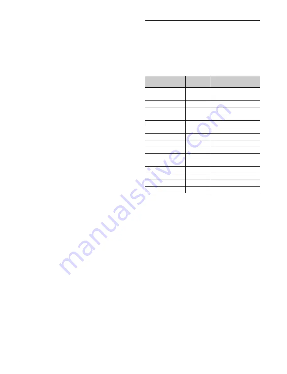
The following pages are included in the USER menu by factory 
default.

For details about the items on each page, see the source 
menu tables in “Menu List” (page 25)
.

The USER MENU CUSTOMIZE menu allows you to add, 
delete, and reorder pages and items in the USER menu to 
make it easier to use.

Editing by item

The USER MENU CUSTOMIZE menu allows you to add a 
new page to the USER menu and add desired items to the 
page.
When shipped, the EDIT page contains factory-preset items, 
but USER 1 EDIT to USER 19 EDIT pages are all blank. You 
can register up to 10 items, including blank lines, on each of 
these pages.

Menu page

USER

menu No.

Source menu / Page No.

<VF OUT>

U01

OPERATION

09

<VF DETAIL>

U02

OPERATION

04

<DYNAMIC FOCUS>

U03

OPERATION

05

<FOCUS ASSIST>

U04

OPERATION

06

<VF DISPLAY>

U05

OPERATION

01

<‘!’ IND>

U06

OPERATION

02

<VF MARKER>

U07

OPERATION

03

<CURSOR>

U08

OPERATION

08

<ZEBRA>

U09

OPERATION

07

<SWITCH ASSIGN1>

U10

OPERATION

11

<SWITCH ASSIGN2>

U11

OPERATION

12

<HEADSET MIC>

U12

OPERATION

14

<OUTPUT FORMAT>

U13

MAINTENANCE

M08

<PROMPTER2 OUT>

U14

MAINTENANCE

M09

<SDI OUT>

U15

MAINTENANCE

M10

<ROM VERSION>

U16

DIAGNOSIS

D03

Содержание CA4000

Страница 1: ...CAMERA SYSTEM ADAPTOR CA4000 OPERATION MANUAL English 1st Edition Revised 1 CAMERA POWER BOOST KIT SKC PB40 ...

Страница 2: ...the Electronic Shutter 15 Setting the Focus Assist Functions 16 Setting the Dynamic Focus Function 17 Setting the Camera Outputs 18 Viewfinder Screen Status Display 19 Menu Operations 20 Menu Display 20 Menu Settings 21 Editing the USER Menu 22 Menu List 25 Menu Tree 25 OPERATION Menu 29 PAINT Menu 34 MAINTENANCE Menu 38 FILE Menu 42 DIAGNOSIS Menu 44 Appendix 45 Precautions 45 Error Messages 45 P...

Страница 3: ... video cameras Knee saturation This compensates the change of hue and decrease in chroma that occur in highlighted areas This enables reproduction of natural skin tones under strong lighting Low key saturation This compensates for saturation in low key zones It compensates for color reproduction in all zones in combination with the matrix color compensation and knee saturation functions Selectable...

Страница 4: ...g any tools This allows the operator to find the right balance when shooting for the lens 2 3 type lens PL mount lens or other diverse lenses mounted on the camera The viewfinder position also slides forward backward together with the handle when a PMW F55 is mounted Assignable buttons Any desired function such as electronic color temperature conversion can be assigned to the assignable button on ...

Страница 5: ...ly power to studio camera lenses c Use an LA FZB2 Mount Adaptor option when using a 2 3 type lens RCP 1000 series Remote Control Panel BNC Video Monitor Waveform Monitor Video Router CCA 5 LAN cable Optical fiber cable Hub RCP 1000 series Remote Control Panel CCA 5 USB flash drive Lens for studio camera a b c CAC 6 Return Video Selector Intercom Headset Microphone CAC 6 Return Video Selector Inter...

Страница 6: ...ra extension unit PMW F55 Solid state Memory Camcorder Optical fiber cable BPU4000 Baseband Processor Unit CA4000 BNC 4 2K Video Monitor DC power supply input BNC 4K Video Monitor Lens Viewfinder HDVF EL75 DVF L700 Viewfinder DVF EL100 DVF L350 RCP 1000 series Remote Control Panel CCA 5 Sync signal input Return video input ...

Страница 7: ...Remote Control Panel BNC Video Monitor Waveform Monitor Video Router CCA 5 LAN cable Optical fiber cable Hub RCP 1000 series Remote Control Panel CCA 5 CAC 6 Return Video Selector Intercom Headset CAC 12 Microphone Holder Microphone USB flash drive Sync signal input Return video input Intercom microphone input F65 Digital Motion Picture Camera BPU4000 Baseband Processor Unit BNC 4 2K Video Monitor...

Страница 8: ...s about attaching see Attaching a Viewfinder page 13 f Handle slide button Releases the handle while this button is pressed allowing the handle to slide when adjusting the position of the handle g Camera mounting screws Attaches the unit to the camera h Microphone holder shoe Attaches to a microphone holder i Handle position lock lever Locks the handle in position Turn the lever counterclockwise t...

Страница 9: ...t microphone on off d Line selector switch Selects the intercom line PROD Producer line ENG Engineer line e INCOM intercom knob Adjusts the intercom audio volume f RET 1 return video 1 button Displays the return video 1 signal in the viewfinder while this button is pressed g RET return video and 2 3 4 return video 2 3 4 selector switch When using other return video systems in parallel with return ...

Страница 10: ...DISPLAY MENU switch Selects the screen displayed in the viewfinder DISPLAY Displays text information and messages showing the operating status center marker safety zone marker and other indicators in addition to the camera image Pressing the menu control button in display mode switches the screen to the status display OFF Displays the image only MENU Displays menu in addition to the camera image l...

Страница 11: ...ry connection connector 12 pin Connects to a lens cable A lens cable connection enables the unit to control lens functions With SKC PB40 attached a DC OUT DC power supply output light On Indicates output from the 3 system DC OUT connector is normal when power is supplied from a CCU Flashing Indicates that the protection circuit for one or two of the three systems has been activated Off Indicates t...

Страница 12: ...iewfinder is still attached the viewfinder will interfere with the handle causing the handle to drop and potentially pinching your fingers 1 Remove the four screws from the top of the video camera and remove the handle from the video camera body 2 Press and hold the handle flip up lock release button and raise the handle of the unit 3 Press the release button 1 to release the catch lever and lift ...

Страница 13: ...rn on the POWER SWITCH of the DVF L700 before turning on the power supply to the unit For details about attaching viewfinders refer to the operating instructions for the viewfinder 1 Loosen the lock ring of the viewfinder shoe align with the slot of the viewfinder then attach the viewfinder by sliding it horizontally 2 Tighten the lock ring after determining the left and right position of the view...

Страница 14: ...the cable clamp belt to the unit using the two supplied B3 8 screws 4 1 Release the buckle 2 wrap the belt around the cable 3 then lock the buckle again 5 Adjust the length by pulling down on the end of the belt Seal Screws B3 8 1 3 2 Optoelectrical cable ...

Страница 15: ...use When the surrounding temperature changes significantly When the gain value is changed using the menu Normally there is no need to adjust the black balance every time the camera is turned on White balance adjustment Always readjust the white balance when lighting conditions change Setting the Electronic Shutter This section explains the shutter modes that can be used with the electronic shutter...

Страница 16: ...item to set and push the knob To use the VF detail signal Set VF DETAIL to ON to add the detail signal to sharp edges in the image You can adjust the signal level strength in the range of 0 to 100 default 25 You can adjust the characteristics of the detail signal using the following items CRISP Removes fine portions of the detail signal FREQUENCY Changes the detection band of sharp edges FLICKER T...

Страница 17: ...too large both the subject and the background are included in the area making the indicator display easily deviate from the subject POSITION Coarse adjustment of the position of the detection area POSITION H Fine adjustment of the position of the detection area in the horizontal direction POSITION V Fine adjustment of the position of the detection area in the vertical direction 4 Turn the menu con...

Страница 18: ...o signals output from the camera using the menu The menu pages used for the output settings are registered in the USER menu by factory default PROMPTER2 OUT SDI OUT Set the menu items on the above menu pages to the settings shown in the following tables For details about menu operations and the USER menu see Menu Operations page 20 Outputting the signal shot by the video camera The same textual in...

Страница 19: ...s turned on b EX lens extender indicator Displayed when using a lens extender c Zoom position indicator Indicates the approximate position of the zoom lens variator between wide angle 0 and telephoto 99 d Battery voltage indicator When the CAMERA POWER switch is set to EXT the DC IN voltage is displayed When the switch is set to CCU the internal voltage of the video camera is displayed e Focus pos...

Страница 20: ...nal level on the CA connector of BPU unit BPUTCCU Optical signal level on the CCU connector of BPU unit BPUtCCU Optical signal level on the CAMERA connector of CCU unit d CHU MODE indicator Displays the current connection status CHU MODE setting page 41 Menu Operations You can make various camera settings using the menu displayed in the viewfinder The following controls are used to operate the men...

Страница 21: ...s often used menu pages selected from among the OPERATION PAINT MAINTENANCE FILE and DIAGNOSIS menus You can edit the factory default menu structure page 22 using the USER MENU CUSTOMIZE menu USER MENU CUSTOMIZE This menu allows you to edit the USER menu items For details see Editing the USER Menu page 22 ALL This menu permits you to control all items of the OPERATION menu PAINT menu MAINTENANCE m...

Страница 22: ...old the menu control knob for 3 seconds when the cursor is displayed to restore the setting to the reference file value If 10 SEC CLEAR has been set to ON on the FILE CLEAR page of the FILE menu you can reset the setting in the reference file for the selected item to the factory set value by pushing and holding the menu control knob for a further 10 seconds To exit the menu Set the DISPLAY MENU sw...

Страница 23: ...item to be moved and push the menu control knob The EDIT FUNCTION screen appears 2 Select MOVE and push the menu control knob The previously displayed page appears again 3 Move the cursor to the position where you wish to move the page and push the menu control knob The item selected in step 1 moves to the position that you selected in step 3 In the above example ASSIGNABLE1 is moved to the top an...

Страница 24: ... screen appears again To delete a page 1 On the EDIT PAGE screen of the USER MENU CUSTOMIZE menu move the cursor to the page to be deleted and push the menu control knob The EDIT FUNCTION screen appears 2 Select DELETE then push the menu control knob The previously displayed page appears again and the message DELETE OK YES NO appears 3 Move the cursor to YES and push the menu control knob To chang...

Страница 25: ...AIL 04 U02 EX ZOOM DISP FOCUS ND CC 5600K IRIS GAIN SHUTTER RETURN TALK MESS AF AGE ND CC 5600K SHUTTER EXT FAN Y TALLY MARKER LEVEL CENTER SAFETY ZONE EFFECT ASPECT MASK SAFETY VF DETAIL CRISP FREQUENCY FLICKER AREA ZOOM LINK COLOR DETAIL DYNAMIC FOCUS PEAK COLOR COLOR SEL CHROMA LEVEL FOCUS ASSIST 06 U04 ZEBRA 07 U09 CURSOR 08 U08 INDICATOR MODE LEVEL GAIN OFFSET AREA MARKER SIZE POSITION POSITI...

Страница 26: ...B PRESET FILE ID CAM CODE DATE 10 SWITCH ASSIGN1 11 U10 VF B SETUP T RESOLUTION CONTRAST BRIGHTNESS PEAKING ASSIGNABLE SW STATUS P01 VIDEO LEVEL P02 COLOR TEMP P03 GAMMA P04 BLACK GAMMA P05 SATURATION P06 KNEE P07 WHITE CLIP P08 DETAIL 1 P09 FLARE GAMMA BLK GAM KNEE WHT CLIP DETAIL LVL DEP SKIN DTL MATRIX BLACK FLARE GAMMA FLARE TEST WHITE AUTO WHITE BALANCE COLOR TEMP BALANCE MASTER LEVEL COARSE ...

Страница 27: ...ANDARD READ WRITE FILE ID CAM CODE DATE FRM AUTO SETUP M01 WHITE SHADING M02 BLACK SHADING M03 AUTO IRIS M04 LENS M05 CALL TALLY M07 OUTPUT FORMAT M08 U13 AUTO BLACK AUTO WHITE AUTO WHITE SHADING AUTO BLACK SHADING TEST V SAW V PARA H SAW H PARA WHITE AUTO WHITE SHADING WHITE SHAD MODE V SAW V PARA H SAW H PARA BLACK MASTER GAIN AUTO BLACK SHADING AUTO IRIS WINDOW OVERRIDE IRIS LEVEL APL RATIO IRI...

Страница 28: ...55 AUDIO SET2 M15 LEVEL OPERATOR FILE F01 SCENE FILE F02 REFERENCE F03 USER GAMMA F04 LENS FILE F05 MATRIX FILE CLEAR F07 F06 READ USB t CAM WRITE CAM t USB READ USB t CAM WRITE CAM t USB PRESET STORE PRESET FILE FILE ID CAM CODE DATE 1 2 3 4 5 STORE STANDARD READ USB t CAM WRITE CAM t USB FILE ID CAM CODE DATE STORE FILE STANDARD ALL PRESET READ USB t CAM WRITE CAM t USB FILE ID CAM CODE DATE REA...

Страница 29: ...S CAM AUDIO SW INFO D06 D07 AUDIO CH1 AUDIO CH2 CH1 MIC 48V CH2 MIC 48V OPERATION Page name Page No Item Settings Description VF DISPLAY 01 U05 EX ON OFF ZOOM ON OFF DISP LEFT RIGT FOCUS ON OFF Valid only when using a serial lens ND ON OFF CC ON OFF 5600K ON OFF IRIS ON OFF GAIN ON OFF SHUTTER ON OFF RETURN ON OFF TALK ON OFF AF ON OFF Displayed only when AF MODE is ON MESSAGE ALL WRN AT OFF ALL D...

Страница 30: ... series viewfinder VF A ON OFF VF B ON OFF WHITE BLACK DOT LEVEL 0 to 100 70 CENTER ON OFF 1 2 3 4 1 Full cross 2 Full cross with hole 3 Center 4 Center with hole SAFETY ZONE ON OFF 80 0 90 0 92 5 95 0 EFFECT ON OFF FOCUS FOCUS Displayed when INDICATOR in FOCUS ASSIST is ON ASPECT ON OFF 16 9 15 9 14 9 13 9 4 3 MASK ON OFF 0 to 15 12 Sets the mask level outside the aspect ratio area SAFETY ON OFF ...

Страница 31: ...0 AREA MARKER ON OFF ASPECT ASPECT Displayed when ASPECT SAFETY in VF MARKER is ON SIZE SMALL MIDDLE LARGE POSITION LEFT CENTER RIGHT POSITION H 0 to 99 50 POSITION V 0 to 99 50 ZEBRA 07 U09 ZEBRA VF A HDVF series viewfinder VF B DVF series viewfinder VF A ON OFF VF B ON OFF 1 2 1 2 ZEBRA1 LEVEL 50 to 109 70 WIDTH 0 to 30 10 ZEBRA2 50 to 109 100 CURSOR 08 U08 CURSOR ON OFF WHITE BLACK DOT LEVEL 0 ...

Страница 32: ...NS VTR S S SY model OFF RETURN1 SW RETURN2 SW INCOM CE model OFF RETURN1 SW RETURN2 SW ENG PROD Assigns a function to the lens VTR START STOP switch HANDLE SW1 SY model OFF RETURN1 SW RETURN2 SW INCOM ZOOM T CE model OFF RETURN1 SW RETURN2 SW ENG PROD ZOOM T HANDLE SW2 SY model OFF RETURN1 SW RETURN2 SW INCOM ZOOM W CE model OFF RETURN1 SW RETURN2 SW ENG PROD ZOOM W ZOOM SPEED 0 to 99 20 Enabled w...

Страница 33: ...KER 16 TRACKER RECEIVE SELECT SEPARATE MIX INTERCOM LEFT RIGHT BOTH SY model only ENG LEFT RIGHT BOTH CE model only PROD LEFT RIGHT BOTH CE model only PGM1 LEFT RIGHT BOTH PGM2 LEFT RIGHT BOTH INPUT LEVEL 20 dBu 0 dBu 6 dBu 0 dBu 6 dBu OUTPUT LEVEL L CH 0 dBu 6 dBu 12 dBu 18 dBu 20 dBu 24 dBu OUTPUT LEVEL R CH OPERATOR FILE 17 READ USBtCAM ENTER to execute Reads the operator file from a USB flash ...

Страница 34: ...E ENTER to execute COLOR TEMP 0 K to 65535 K 3200 K BALANCE 99 to 99 0 MASTER 3 0 dB to 12 0 dB 0 0 dB GAMMA P04 LEVEL R G B M 99 to 99 0 R G B and M master values can be independently set COARSE 0 35 to 0 90 0 05 steps 0 45 TABLE STANDARD HYPER USER 1 2 3 4 5 6 7 When STANDARD or USER is selected USER 1 to 5 only 1 Camcorder equivalent 2 4 5 gain 3 3 5 gain 4 SMPTE 240M equivalent 5 ITU R709 equi...

Страница 35: ...ighted ABS absolute value mode DETAIL 1 P09 DETAIL ON OFF LEVEL 99 to 99 0 Absolute value is displayed in ABS mode LIMITER M 99 to 99 0 LIMITER WHT 99 to 99 0 Absolute value is displayed in ABS mode LIMITER BLK 99 to 99 0 Absolute value is displayed in ABS mode CRISP 99 to 99 0 Absolute value is displayed in ABS mode LEVEL DEPEND 99 to 99 0 Absolute value is displayed in ABS mode ON OFF ABS Highli...

Страница 36: ... 2 3 The skin gate function can be turned on for the specified channel only MAT Displayed when GATE in MULTI MATRIX is ON ABS Highlighted ABS absolute value mode NATURAL SKINDTL OFF ON ZOOM LINK OFF ON TELE 0 to 99 WIDE 0 to 99 CH SW 1 ON 2 3 ON OFF Sets the skin tone detail function independently for each channel channel 1 is always ON Absolute value is displayed for LEVEL only in ABS mode HUE 1 ...

Страница 37: ...0 1 500 1 1000 1 2000 1 4000 59 94i 1 100 1 120 1 125 1 250 1 500 1 1000 1 2000 1 4000 50P 1 60 1 100 1 120 1 125 1 250 1 500 1 1000 1 2000 50i 1 60 1 100 1 120 1 125 1 250 1 500 1 1000 1 2000 29 97P 1 50 1 60 1 120 1 125 1 250 1 500 1 1000 1 2000 25P 1 30 1 50 1 60 1 100 1 250 1 500 1 1000 1 2000 24P 23 98P 1 48 1 50 1 60 1 120 1 250 1 500 1 1000 1 2000 Shutter step selection ECS FREQ 59 94P 1 60...

Страница 38: ...y MAINTENANCE Page name Page No Item Settings Description AUTO SETUP M01 AUTO BLACK ENTER to execute Disabled when CHU MODE is set to F65 AUTO WHITE ENTER to execute AUTO WHITE SHADING ENTER to execute AUTO BLACK SHADING ENTER to execute Disabled when CHU MODE is set to F65 TEST OFF SAW 10STEP WHITE SHADING M02 V SAW R G B 99 to 99 0 R G and B values can be independently set V PARA R G B 99 to 99 ...

Страница 39: ...icator on the panel when AUTO IRIS is off CONTROL Displays the value from the camera RETURN Displays the return value from the lens When AUTO IRIS is on always displays the return value from the lens LENS AUX ON OFF ON When a lens is connected to the AUX connector on the rear panel The CA unit must be rebooted after changing settings CAM LENS IF OFF Type C Type A Type C 12P Type A 12P Sets the typ...

Страница 40: ...sync status GENLOCK ENABLE DISABLE Not displayed when a CCU or BPU is connected STATUS FORMAT PHASE V 1024 to 1023 0 H 1700 to 1700 0 AUDIO INPUT SEL M13 AUDIO IN F55 CA MIC F55 AES CA Selects the audio signal input Only CA is enabled when CHU MODE is set to F65 F55 AUDIO SET1 M14 INPUT Enabled only when CHU MODE is set to F55 MIC CH1 REF 60dB 50dB 40dB Selects the reference input level when the A...

Страница 41: ... STEREO Channels adjusted in stereo mode DATE M16 DATE TIME 2000 to 2099 01 to 12 00 to 31 00 to 23 00 to 59 FILE TIMESTAMP FORMAT 1 Y Mn D 2 Mn D 3 D M Y 4 D M 5 M D Y 6 M D Y Year Mn Month numeric Mn Month English abbreviation D Day CHU MODE M17 CURRENT PMW F55 F65 1x 2x Currently selected camera head setting PMW F55 ENTER to execute Sets camera head unit to PMW F55 F65 1x 2x ENTER to execute Se...

Страница 42: ...ter executing STORE To read a file specify the file number only 2 3 4 5 STORE ENTER to execute STANDARD ENTER to execute Loads the standard paint data READ USBtCAM ENTER to execute Reads five scene files from a USB flash drive into internal memory WRITE CAMtUSB ENTER to execute Writes five scene files from internal memory to a USB flash drive FILE ID 16 characters max Enters a comment in the scene...

Страница 43: ...asing the value moves the position downwards H POS 20 to 20 0 V POS 20 to 20 0 STORE ENTER to execute MATRIX F06 CUSTOMIZE 1 2 3 4 5 ENTER to execute Stores the current multimatrix data in the custom matrix file in internal memory CUSTOMIZE CLEAR ENTER to execute Clears the custom matrix file stored in internal memory READ USBtCAM ENTER to execute Reads the matrix file from a USB flash drive WRITE...

Страница 44: ...xxxx OPTION Displays option functions if any option is installed CAM INFO D05 MODEL PMW F55 F65 Displays the connected camera setting STATUS OK NG Displays the camera status POWER ON OFF Displays the camera s power supply status CONNECT OK NG Displays the status of connections with the camera INTERNAL ND CLEAR 0 9 1 8 Displays the status of the PMW F55 internal ND filter Displayed only when CHU MO...

Страница 45: ...ises moisture may form on the outer surface of the unit and or inside of the unit This is known as condensation If condensation occurs turn off the unit and wait until the condensation clears before operating the unit Operating the unit while condensation is present may damage the unit Error Messages If a problem occurs during operation the following messages may be displayed Note To display a mes...

Страница 46: ... to the upper limit CAM 12V BATTERY NEAR END The voltage of the 12 V supply has fallen to the specified Near End value CAM 24V BATTERY NEAR END The voltage of the 24 V supply has fallen to the specified Near End value CAM OPTICAL LEVEL CARE The optical level received on the SKC 4065 camera connector has fallen to critical level Error CAM DIGITAL VF ERROR The DVF EL100 has failed Status CAM 12V BAT...

Страница 47: ...0 2 A max Operating temperature 0 C to 40 C 32 F to 104 F Storage temperature 20 C to 60 C 4 F to 140 F Mass Approx 2 5 kg 5 lb 8 2 oz unit only Dimensions 147 221 350 mm 5 7 8 8 3 4 13 7 8 in W H D see page 49 Input output connectors BPU Optoelectrical connector 1 AUX 12 pin 1 VF A 20 pin round type 1 VF B 26 pin rectangular type 1 AUDIO IN XLR 3 pin female 1 When the AUDIO is set to MIC 60 dBu c...

Страница 48: ...180 V DC 1 0 A max Operating temperature 0 C to 40 C 32 F to 104 F Storage temperature 20 C to 60 C 4 F to 140 F Mass Approx 0 7 kg 1 lb 8 7 oz Dimensions 112 196 40 mm 4 1 2 7 3 4 1 5 8 in W H D Output connectors DC OUT XLR 4 pin 2 14 V 6 5 A 4 pin 1 24 V DC 3 7 A 135 W 3 system maximum output power Notes Always verify that the unit is operating properly before use SONY WILL NOT BE LIABLE FOR DAM...

Страница 49: ...49 Specifications Dimensions Units mm inches 147 5 7 8 221 8 3 4 350 13 7 8 108 4 3 8 ...

Страница 50: ... for use by the purchasers of the equipment described in this manual Sony Corporation expressly prohibits the duplication of any portion of this manual or the use thereof for any purpose other than the operation or maintenance of the equipment described in this manual without the express written permission of Sony Corporation ...

Страница 51: ...CA4000 JN SY CE 4 479 641 12 1 2013 Sony Corporation ...

Отзывы: