6 (E)
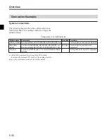
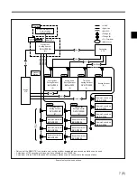
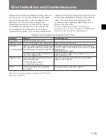
Configuration of an S-BUS data link
Station name
Equipment
Quantity
Function
Primary station Routing switcher DVS-V3232B (M), BVS-A3232(M)
a),
etc. 1
Communication control in the data link
Secondary
Control unit BKS-R3204, BKS-R3205, BKS-R3206, etc.
253 max.
Communication control in each
station
Routing switcher BVS-V3232 (S), BVS-A3232 (S)
a)
, etc.
equipment
Terminal
Computer with Windows 3.1 or communication software
1
Setting needed for system configuration
installed
The following diagram shows the configuration of an
S-BUS data link with a routing switcher serving as the
primary station.
Connection Examples
System connections
a) (M) and (S) represent the setting of the M/S switch
located on the internal CPU board of the routing switcher.
Refer to the maintenance manual for further details.
Overview


