background image

7-16

HDS-7150/7100

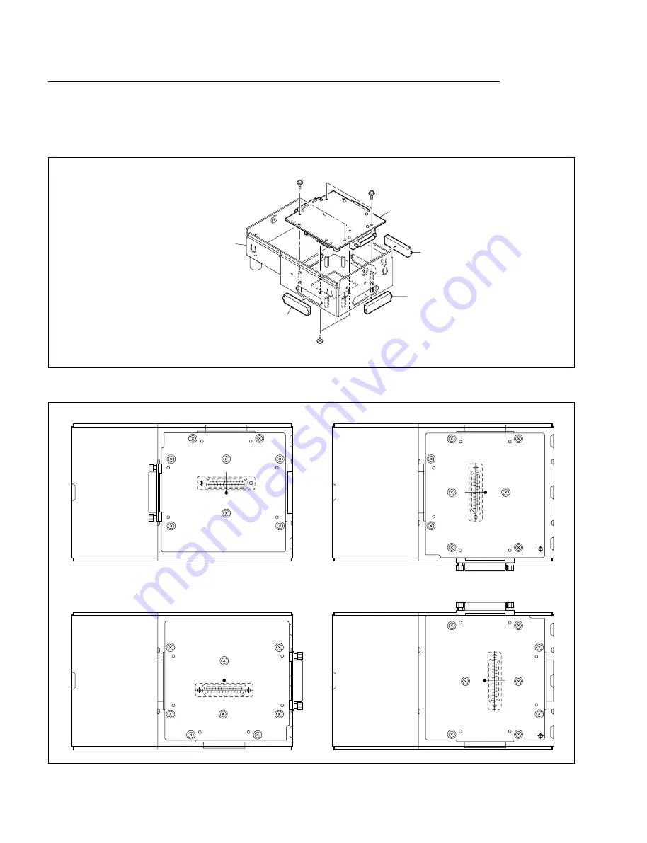
Type-A (Factory setting)

Type-C

Type-B

Type-D

CN7

CN4

CN8

IF-629 board

CN7

CN8

CN4

IF-629 board

CN8

CN7

IF-629 board

CN4

CN4

CN7

IF-629 board

CN8

Removal and Installation of IF-629 Board

(1) Remove the AD panel.

(Refer to step (1) in “7-2-4. Installation of BKDS-7030/7031/7033”

(2) Remove the caps and the three connectors, and remove the IF-629 board.

(3) Install the IF-629 board according to the type using the six screws as shown.

(4) Install the three connectors and the caps except CN4 on the IF-629 board.
(5) Install the AD panel to the adaptor box.

Cap

Cap

Cap

PSW3 

x

 8

PSW3 

x

 8

B3 

x

 5

Adaptor box

IF-629 board

7-2. Installation of Options for BKDS-7071

Содержание BKDM-3010

Страница 1: ...IDEO SWITCHER HDS 7150 7100 HKDS 7695 7695A POWER SUPPLY UNIT SWITCHER CONTROL PANEL BKDS 7017 2010 DME CONTROL PANEL BKDM 3010 BKDS 7030 BKDS 7031 BKDS 7033 BKDS 7075 BKDS 7091 HKDS 7031 HKDS 7051 HKDS 7061 HKDS 7071 HZS 7040 HZS 7060 BKDS 7001 BKDS 7003 ...

Страница 2: ...only To reduce the risk of electric shock fire or injury do not perform any servicing other than that contained in the operating instructions unless you are qualified to do so Refer all servicing to qualified service personnel WARNUNG Die Anleitung ist nur für qualifiziertes Fachpersonal bestimmt Alle Wartungsarbeiten dürfen nur von qualifiziertem Fachpersonal ausgeführt werden Um die Gefahr eines...

Страница 3: ...ing When this product is installed in a rack please make sure that the rack does not achieve hazardous condition due to uneven mechanical loading 1 P HDS 7150 7100 WARNING For HKDS 7695A THIS APPARATUS MUST BE EARTHED a An equipment grounding conductor that is not smaller in size than the ungrounded branch circuit supply conductor is to be installed as part of the branch circuit that supplies the ...

Страница 4: ......

Страница 5: ...ion 1 5 2 Installation of HDS 7150 7100 2 1 External Dimensions 2 1 2 2 Rack Mounting 2 2 2 3 Matching Connectors 2 7 2 3 1 HDS 7150 2 7 2 3 2 HDS 7100 2 8 2 4 Input and Output Signals of Connectors 2 9 2 5 Removal of Front Panel 2 14 2 6 Removal of Parts on the Front Side 2 15 2 7 Description of Switches and LEDs on Boards 2 16 2 7 1 Power Indicators on CKG 26 CPU 183 CRK 9 DI 37 DLP 17 DSK 16 ME...

Страница 6: ... 6 Opening and Closing of Panel 4 6 4 7 Description of Switches and LEDs on Boards 4 7 4 7 1 CPU 246 Board 4 7 4 7 2 CN 1150 Board 4 9 4 7 3 RE 146 Board BKDS 7071 7091 4 10 4 8 Adjustment of Fader Lever 4 11 4 9 Installation of Switch Tip accessory 4 12 4 10 Hard Reset 4 13 5 Installation of BKDS 2010 5 1 External Dimensions 5 1 5 2 Installation Space 5 2 5 3 Installation in Console 5 3 5 4 Match...

Страница 7: ...Boards 7 5 7 1 4 Installation of HKDS 7031 7061 7071 7 7 7 1 5 Installation of HKDS 7051 7 8 7 2 Installation of Options for BKDS 7071 7 9 7 2 1 Turning On Off the Power 7 9 7 2 2 Installation of BKDS 7001 7 10 7 2 3 Installation of BKDS 7003 7 11 7 2 4 Installation of BKDS 7030 7031 7033 7 13 7 2 5 Joining of BKDS 7075 7 15 7 2 6 Connection of BKDS 7017 and BKDS 7075 7 19 7 2 7 Installation of BK...

Страница 8: ...he GPI Output 9 19 9 3 14 Setting of the Operation Mode 9 20 9 4 Saving Set up Data to Nonvolatile Memory 9 21 10 Set up of HDS 7100 10 1 Overview of Operating Saving the Set up Data 10 1 10 2 Installation of Program 10 3 10 2 1 Downloading the Program 10 3 10 2 2 Initializing the Nonvolatile Memory 10 6 10 3 Set up 10 8 10 3 1 Confirmation of the Software Version 10 9 10 3 2 Setting about the Sys...

Страница 9: ...HDS 7150 7100 This manual describes the information for the periodic maintenance and the information for the service with predicated on the replacement of the principal blocks and mounted circuit boards Maintenance Manual Part2 Available on request Volume1 Service instruction Volume2 Spare parts list Semiconductors list Block diagrams Frame wiring and Board layouts These manuals describe the detai...

Страница 10: ...llation of BKDM 3010 These sections describe the external dimensions installing in console BKDS 7017 2010 connectors input and output signals of connectors description of switches and LEDs on boards replacing the switch tips BKDS 7017 2010 and installing the track ball BKDM 3010 Section 7 Installation of Options This section describes the installation slot of plug in boards plug in boards list and...

Страница 11: ...essible disconnect device in the fixed wiring so that the operator engineer can turn off the power in case a fault should occur 1 2 2 Power Specifications Power requirements HKDS 7695 AC 100 to 120 V 10 50 60 Hz HKDS 7695A AC 100 to 240 V 10 50 60 Hz HDS 7150 7100 DC 5 0 0 2 V DC _5 0 0 2 V DC 12 0 0 2 V DC 3 3 0 2 V Current consumption HKDS 7695 30 A 100 V max to 25 A 120 V max HKDS 7695A 30 A 10...

Страница 12: ...m w Use of the following power cords is recommended when the machine is used in the European countries 1 2 Power Supply AC inlet For the customers in the all European countries except the United Kingdom Required Parts Power Cord 250 V 10 A 2 0 m 1 551 631 22 For HKDS 7695 7695A AC power cord 125 V 15 A 2 5 m 1 775 981 11 Supplied with HKDS 7695 7695A AC inlet Main unit 1 Harness A MB PA2 1 959 943...

Страница 13: ...The HDS 7150 7100 and the HKDS 7695 7695A are connected using the two specified DC power supply cord harness A MB PA2 and harness B MB PB2 that are supplied with the HKDS 7695 7695A 1 Connect the two AC power cords supplied with the HKDS 7695 7695A to an AC power source of 100 V to 120 V n Connect the two AC power cords to the same AC power source 2 Connect the PROCESSOR A connector of the HKDS 76...

Страница 14: ...2 2 2 2 2 2 2 PS3 PS3 PWH3 PWH3 PWH3 PWH3 2 PWH4 PWH4 PWH4 4 4 4 4 4 4 ELCO 8070 PBT GF30 ELCO 8070 PBT GF30 B3 PS3 PS3 2 2 2 2 2 2 2 2 2 2 2 PS3 PS3 PWH3 PWH3 PWH3 PWH3 2 HKDS 7695 7695A Power supply unit HKDS 7695 7695A Power supply unit Harnesses A MB PA2 Harnesses B MB PB2 PROCESSOR B connectors POWER SUPPLY 1 B connector POWER SUPPLY 1 A connector Blank panel PROCESSOR A connectors AC 100 V t...

Страница 15: ...VTR MONITOR WFM SWITCHER PANEL SWER PANEL 2 REMOTE 3 1 2 3 4 5 6 7 8 9 10 11 12 13 14 15 SWITCHER PANEL DME PVW CLEAN AUX1 AUX2 AUX3 AUX4 AUX5 EXT DME1 EXT DME2 EDITOR A REMOTE 1 EDITOR B REMOTE 2 SERIAL TALLY REF INPUT SWITCHER GPI REF OUTPUT EDITOR DME ME ME PVW PGM PRIMARY INPUTS VTR SWER A B EDITOR BVE 9100 REF INPUT INPUT OUTPUT HD Routing Switcher TALLY SYSTEM HD SDI RS 422A HDS 7150 DME GPI...

Страница 16: ...E CONTROL PANEL BKDM 3010 MONITOR MONITOR WFM PANEL 2 REMOTE 3 1 2 3 4 5 6 7 8 9 10 PVW CLEAN AUX1 EDIT PVW EXT DME1 EDITOR A REMOTE 1 EDITOR B REMOTE 2 SERIAL TALLY REF INPUT SWITCHER GPI REF OUTPUT EDITOR DME PGM PRIMARY INPUTS VTR SWER A B EDITOR BVE 9100 REF INPUT INPUT OUTPUT HD Routing Switcher TALLY SYSTEM HD SDI RS 422A HDS 7100 DME GPI DME PANEL 1 2 3 4 1 2 3 4 5 HD VTR INPUT OUTPUT REMOT...

Страница 17: ... HDS 7150 7100 Unit mm Section 2 Installation of HDS 7150 7100 2 1 External Dimensions 620 14UNIT 23 5 40 40 482 29 29 424 465 582 492 40 7 13 13 29 29 13 28 6 310 488 132 47 7 403 2 13 250 8 111 1 75 350 ...

Страница 18: ...nt its fall c Be sure to use the recommended rail when rack mounting The unit cannot be fixed completely to a rack by rack angles alone Be sure to mount in the rack with two person or more m If the HDS 7150 7100 are mounted in the 19 inch standard rack it is recommended to install a ventila tion fan to prevent a temperature rise in the rack Make sure that all the units in the rack should be operat...

Страница 19: ...M 18DV 2 Secure the four inner members to the HDS 7150 7100 by the 32 screws B4 x 8 supplied with the RMM 18DV 3 Remove the feet of the HDS 7150 7100 as required HDS 7150 7100 2 2 Rack Mounting Inner member Stopper Outer member 1 B4 x 8 Feet Inner members Inner member Inner member HDS 7150 7100 ...

Страница 20: ...2 the two washers W4 and the plate nut short supplied with the RMM 18DV Adjust the installation position of the outer member assembly to meet the specification shown in the figure After the adjustment tighten the screws B4 x 8 temporarily secured in the step 4 HDS 7150 7100 2 2 Rack Mounting C4 x 12 W4 Outer member 1 Bracket Rack TOP VIEW Spec 50 _0 Plate nut short 5 Brackets Plate nut long Outer ...

Страница 21: ...mbers 7 After confirming that the unit can be moved smoothly tighten the screws temporarily secured in the step 5 HDS 7150 7100 2 2 Rack Mounting HDS 7150 7100 Outer member 2 Rack Stopper Inner members When housing the set shift the slide bearing as illustrated Inner member Outer member 2 Slide bearing ...

Страница 22: ...t ornamental washers When HDS 7150 7100 is mounted in a rack the maximum moving distance is illustrated below HDS 7150 7100 2 2 Rack Mounting Rack Rack RK5 x 16 RK5 x 16 Ornamental washer Ornamental washer Rack angle Bracket Outer member TOP VIEW Unit mm 620 488 132 Distance to slide rail center Set height when mounted in rack Maximum moving distance 569 ...

Страница 23: ...7 11 PRIMARY INPUTS 1 to 15 BNC Coaxial Connector Plug REF INPUT REF OUTPUT REF B B INPUT AUX BUS OUTPUTS 1 to 5 EDIT PVW OUTPUTS ME OUTPUTS 1 2 PGM OUTPUTS 1 to 3 CLEAN OUTPUT PVW OUTPUT ME PVW OUTPUT POWER SUPPLY 1 A B DC Power Supply Cords Harness A MB PA2 POWER SUPPLY 2 A B Harness B MB PB2 For the details of the power supply cord refer to Section 1 2 3 1 The following solderless contact must ...

Страница 24: ...563 376 11 SWITCHER GPI DME GPI D sub 25 pin Male DME PANEL Connector 25 pin Male 1 560 904 11 1 Junction Shell 25 pin 1 563 377 11 PRIMARY INPUTS 1 to 10 BNC Coaxial Connector Plug REF INPUT REF OUTPUT REF B B INPUT AUX BUS OUTPUT 1 EDIT PVW OUTPUTS PGM OUTPUTS 1 to 3 CLEAN OUTPUT PVW OUTPUT POWER SUPPLY 1 A B DC Power Supply Cords Harness A MB PA2 Harness B MB PB2 For the details of the power su...

Страница 25: ...pin positions of the connectors HDS 7150 7100 2 4 Input and Output Signals of Connectors 1 13 4 56 55 1 52 49 54 53 14 25 D sub 25 pin Female EXT VIEW EXT VIEW EXT VIEW EXT VIEW D sub 56 pin Female 1 8 9 15 D sub 15 pin Female 1 2 3 1 1 2 3 4 5 1 2 3 4 5 6 7 8 9 13 14 15 10 11 12 2 D sub 9 pin Female 1 5 6 9 B B POWER SUPPLY 2 POWER SUPPLY 1 A A POWER SUPPLY 1 EDIT PVW OUTPUTS HDS 7150 Rear panel ...

Страница 26: ...HDS 7100 Rear panel Pin position EDIT PVW OUTPUTS EXT VIEW 1 13 4 56 55 1 52 49 54 53 14 25 D sub 25 pin Female EXT VIEW D sub 56 pin Female EXT VIEW 1 8 9 15 D sub 15 pin Female 1 1 2 3 1 2 3 4 5 6 7 8 9 10 D sub 9 pin Female EXT VIEW 1 5 6 9 B POWER SUPPLY 1 A POWER SUPPLY 1 ...

Страница 27: ...Name Function 1 FG Frame ground 2 SERIAL TALLY RX A Received data _ 3 SERIAL TALLY TX B Transmitted data 4 GND Common ground 5 _ _ 6 GND Common ground 7 SERIAL TALLY RX B Received data 8 SERIAL TALLY TX A Transmitted data _ 9 FG Frame ground n The CONTROLLER indicates the controlling device The DEVICE indicates the controlled device POWER SUPPLY 1 A 2 A D sub 56 pin Female DEVICE from HKDS 7695 76...

Страница 28: ...ted data 4 DTR Data terminal ready 4 5 SG Signal ground 6 DSR Data set ready 4 7 RTS Request to send 8 CTS Clear to send 9 _ _ 4 Pins 1 4 and 6 are short circuited each other on the CN 1819 board EXT DME 1 2 RS 422A D sub 9 pin Female DEVICE from HD Digital Multi Effects HDME 7000 etc Pin No Signal Name Function 1 FG Frame ground 2 DME 1 to 4 TX A Transmitted data _ 3 DME 1 to 4 RX B Received data...

Страница 29: ...and B example 7 pin and 19 pin of same number constitute a pair of relay contacts HDS 7150 7100 2 4 Input and Output Signals of Connectors Relay GPI OUT n B GPI OUT 5 8 GPI OUT COM Open collector output n 1 4 V GPI OUT n A 5 6 DME PANEL RS 422A D sub 25 pin Female to Adaptor Box BKDS 7075 Pin No Signal Name Function 1 GND Ground 2 12 V Power supply 12 V 3 SCLK Serial clock for switch read and LED ...

Страница 30: ...emoval of Front Panel 1 Loosen the six fixing screws on the front panel n The screws have the drop safe 2 Remove the front panel in the direction of the arrow HDS 7150 7100 2 5 Removal of Front Panel Fixing screws Front panel ...

Страница 31: ...nnectors CN2 from the CN 1700 boards 4 Remove the eight screws on the two fan assemblies To install the parts on the front side carry out in the reverse order of the steps 1 through 4 HDS 7150 7100 2 6 Removal of Parts on the Front Side Board holder PWH4 x 8 PWH4 x 8 PWH4 x 8 PWH4 x 8 PWH4 x 8 Fan assembly Fan assembly CN 1700 board CN 1700 board CN2 CN2 Board retainer PWH4 x 8 Board retainer PWH4...

Страница 32: ...pective boards are shown below The boards are listed in the order of slots Power voltage Display LED 5 V 3 V _5 V 12 V _2 V Board Name VCC VDD VEE CPU 183 D6 Q 5 D7 Q 5 D5 Q 5 CKG 26 D13 Q 2 D14 Q 4 D15 Q 3 VSE 19 HKDS 7061 D1 Q 11 D6 Q 11 DLP 17 HKDS 7061 D3 Q 11 D4 Q 11 CPU 183 HKDS 7071 D6 Q 5 D7 Q 5 D5 Q 5 MPU 111 HKDS 7071 D1 Q 2 D2 Q 3 MEM 65Y HKDS 7071 D3 R 11 D4 R 11 MEM 65C HKDS 7071 D3 R...

Страница 33: ... _2 V on the DI 37 and OUT 20 boards are generated by the DC to DC coverter on the respective boards CPU 183 VSE 19 DLP 17 MEM 65Y MEM 65C MEM 65K VSE 20 MIX 43 VSE 21 CRK 9 WKG 29 VSW 66 DSK 16 DI 37 OUT 20 CKG 26 D5 D6 D7 D1 D2 D3 D4 D3 D4 D3 D4 D2 D4 D2 D3 D1 D2 D39 D40 D1 D2 D13 5 V D14 3 V D15 _ 5 V 12 V 5 V 3 V VCC VDD VEE 5 V 3 V 5 V 3 V 5 V 3 V 5 V 3 V 5 V 3 V D3 D4 5 V 3 V D3 D4 5 V 3 V D...

Страница 34: ...t to the 5 V A 3 V and _5 V TEST terminals D16 D17 D18 D19 D20 D21 D22 Q 3 D23 D24 D25 D26 D27 and D28 Q 4 Operating status indication These LEDs are used for the factory setting D29 Q 4 PLL lock indication This LED lights when internal PLL circuit locks to the reference signal that is input to the REF INPUT connector on the rear panel When this LED flashes set the field frequency correctly using ...

Страница 35: ...ion COP2 COP3 COP4 COP5 COP6 and COP7 P 7 Mode setting connector pin These jumpers are used for the factory setting Connect the pin headers as shown in the figure on the previous page CN5 M 3 and CN8 Q 7 Connectors for the factory setting These connectors are used for the factory setting ON 1 2 3 4 5 6 7 8 HDS 7150 7100 2 7 Description of Switches and LEDs on Boards ...

Страница 36: ...ates the knob position S2 Q 5 RESET switch Use the RESET switch to re start forcibly the system by means of hardware When this switch is pressed the HDS 7150 7100 perform the same operation as the power on sequence However the resume function is not operated CN8 Q 2 CN9 Q 3 and CN10 Q 4 Connectors for the factory setting These connectors are used for the factory setting ON 1 2 3 4 A side Component...

Страница 37: ...ut to the PRIMARY INPUTS has errors The LEDs from D20 to D34 correspond to PRIMARY INPUT 1 to PRIMARY INPUT 15 respectively A side Component side HDS 7150 7100 2 7 Description of Switches and LEDs on Boards D20 D21 D22 D1 D2 D3 D4 D35 CRCC 1 2 3 4 5 6 7 8 9 10 11 12 13 14 15 GND D23 D24 D25 D26 D27 D28 D29 D30 D31 D32 D33 D34 5 V _3 V _5 V _2 V 1 2 V A B 5 V 3 V _5 V _2 V A B A B C Top side Front ...

Страница 38: ......

Страница 39: ...3 1 HDS 7150 7100 Unit mm Section 3 Installation of HKDS 7695 7695A 3 1 External Dimensions 626 44 542 40 7 29 29 132 3UNIT 23 5 40 40 482 29 29 424 465 101 6 73 7 304 8 254 44 22 75 350 ...

Страница 40: ...CAUTIONS Be sure to use the recommended rail when rack mounting The unit cannot be fixed completely to a rack by rack angles alone Be sure to mount in the rack with two person or more m If the HKDS 7695 7695A is mounted in the 19 inch standard rack it is recommended to install a ventila tion fan to prevent a temperature rise in the rack Make sure that all the units in the rack should be operated w...

Страница 41: ...f the RMM 30 2 Secure the two inner members to the HKDS 7695 7695A by the six screws B4 x 8 supplied with the RMM 30 3 Remove the feet of the HKDS 7695 7695A HKDS 7695 7695A 3 2 Rack Mounting Outer member Stopper Inner member Feet B4 x 8 B4 x 8 Inner member Inner member HKDS 7695 7695A ...

Страница 42: ...nt and rear brackets 5 Temporarily secure the front and rear brackets to the outside of the rack by the eight screws B 5 x 8 supplied with the RMM 30 HKDS 7695 7695A 3 2 Rack Mounting 31 75 12 7 31 75 Rack Rack B 5 x 8 Front bracket Rear bracket Outer members B 5 x 8 12 7 12 7 Rear bracket Outer member Front bracket ...

Страница 43: ...be moved smoothly tighten the screws temporarily secured in the step 5 n A combination of the HKDS 7695 and the HKDS 7695A is not allowed Use two power supply units of the same model HKDS 7695 7695A 3 2 Rack Mounting When using the two units of HKDS 7695 7695A Used for redundant power supply Outer member Rack HKDS 7695 7695A Inner members Stoppers ...

Страница 44: ...amental washers When the HKDS 7695 7695A is mounted in a rack the maximum moving distance is illustrated below HKDS 7695 7695A 3 2 Rack Mounting Rack Rack RK5 x 16 RK5 x 16 Ornamental washer Ornamental washer Rack angle Bracket Outer member TOP VIEW 132 66 Distance to slide rail center Set height when mounted in rack Maximum moving distance 569 Unit mm ...

Страница 45: ... 7695A using the eight screws PSW4 x 8 supplied with the HKDS 7695 7695A 2 Fix the HKDS 7695 7695A to wall or other secure fixture by routing the chain through the hole of the connecting metal to prevent the HKDS 7695 7695A from falling 3 4 Matching Cables Connector indication on rear panel Cable AC IN AC Power Supply Cord For the details of the power supply cord refer to Section 1 2 3 PROCESSOR A...

Страница 46: ... 25 43 GND Frame ground 45 47 49 51 44 48 12 V Power supply 12 V 52 _5 V Power supply _5 V 53 5 V B SENS 5 V B Sense 54 5 V B SENS_ 5 V B Sense_ 55 12 V SENS 12 V Sense 56 12 V SENS_ 12 V Sense_ n The DEVICE indicates the controlled device PROCESSOR A D sub 56 pin Female DEVICE from HDS 7150 7100 Pin No Signal Name Function 1 5 V C SENS 5 V C Sense 2 6 9 11 5 V A Power supply 5 V A 13 28 31 32 3 4...

Страница 47: ... TOP MENU UTILITY 385 30 15 51 15 110 76 8 24 10 OPTION PANEL REMOTE 1 SWITCHER REMOTE 2 DME TERMINAL 1 REMOTE 3 REMOTE 4 TERMINAL 2 14 30 14 30 760 850 496 9 6 5 1 9 6 5 1 9 6 5 1 9 6 5 1 9 6 5 1 9 6 5 1 9 6 5 1 25 14 13 1 9 6 5 1 SEE INSTRUCTION MANUAL DOWNSTREAM KEYER Unit mm 4 1 External Dimensions ...

Страница 48: ...tion Space to Console The BKDS 7017 can be installed in the console by drilling the holes of the following specifications in the console 185 185 11 M4 185 185 418 824 854 418 9 9 15 43 15 198 198 470 52 500 15 483 110 7 2 10 about 75d Unit mm BKDS 7017 4 1 External Dimensions 4 2 Installation Space to Console ...

Страница 49: ...onnectors on the rear panel at the time of installing connecting or servicing connect the following connectors or their equivalents Connector indication on rear panel Connector parts No and name cable side SWITCHER D sub 9 pin Male DME Connector 9 pin Male 1 560 651 00 1 TERMINAL 1 2 Junction Shell 9 pin 1 561 749 00 REMOTE 1 to 4 OPTION PANEL BVS Cable 1 574 993 11 AC IN Power Supply Cord For the...

Страница 50: ...ta 8 TX A Transmitted data _ 9 _ _ 1 BKDS 7001 Option IF 523 board is required for the REMOTE 1 to 4 TERMINAL 1 2 RS 232C D sub 9 pin Female to Terminal Pin No Signal Name Function 1 DCD Received line signal detector signal 2 2 RX Received data 3 TX Transmitted data 4 DTR Data terminal ready signal 2 5 GND Signal ground 6 DSR Data set ready signal 2 7 RTS Request to send signal 3 8 CTS Clear to se...

Страница 51: ...y 9 TWDT Indicate data for character display 10 GND Ground 11 TBLANK Disable signal for character display 12 GND Ground 13 GND Ground 14 12 V Power supply 12 V 15 12 V Power supply 12 V 16 BLANK LED light disable signal 17 GND Ground 18 SEQ Control signal for switch read and LED light 19 RDT Switch read data 20 GND Ground 21 TSEQ Control signal for character display 22 TQCLK Control signal for cha...

Страница 52: ...anel 2 Move the slide knobs forward and release the locks 3 Push up the panel and open it 4 Close the panel and push down the panel until the slide knobs are locked 5 Tighten the screws of the slide knobs at both sides of the panel Slide knob Slide knob Panel Slide knob BKDS 7017 4 6 Opening and Closing of Panel ...

Страница 53: ...djustment in the factory S1 R 10 RESET switch This switch is used to forcibly restart the SYSTEM by the hardware The BKDS 7017 performs the same operation as the power on sequence S2 R 19 ABORT switch This switch is used for the adjustment in the factory S3 R 10 SUB ABORT switch This switch is used for the adjustment in the factory n If pressing this switch when the S5 switch on the CPU 246 board ...

Страница 54: ... Just after turning on the power the system starts up Selection 2 under normal status When starting up the system diagnosis program runs After turning on the power it is necessary for about ten seconds until the system starts up S5 N 1 SUB CPU switch This switch is used to select the operation mode of SUB CPU Factory setting All OFF n indicates the knob position 1 Selection under normal status Set...

Страница 55: ...is LED lights D3 Yellow A 1 When the 12 V source provides to the CN4 on the CN 1150 board this LED lights D4 Yellow D 1 When the 12 V source provides to the CN5 through CN18 on the CN 1150 board this LED lights D5 Green D 1 When the 5 V source provides to the CN5 through CN18 on the CN 1150 board this LED lights D3 D1 D2 D4 D5 A side Component side BKDS 7017 4 7 Description of Switches and LEDs on...

Страница 56: ...r Supply Units are Used When the power switch in the panel is turned off When the fun stops in the power supply unit When one or more of the DC DC converters CP2 and CP3 and AD DC converter CP1 is not operating correctly When the voltage of the two power supplies is not correctly adjusted The LED of the power supply unit whose voltage is low lights off The LED D9 of the power supply unit that is n...

Страница 57: ...and then remove the AD panel Refer to step 1 in 7 2 4 Installation of BKDS 7030 7031 7033 3 Turn the screw by an L shaped hex wrench across 4 0 mm and adjust the operating force 2 If turning the screw clockwise the operating force of the fader lever becomes heavier 3 If turning the screw counterclockwise the operating force of the fader lever becomes lighter BKDS 7017 4 8 Adjustment of Fader Lever...

Страница 58: ...e gap between key and sides 2 Hold the key top to remove it 3 Pull the cap pull tool with holding the cap and remove the diffusion plate switch tip and key top 4 Insert the switch tip key top sheet between diffusion plate milky white color and key top clear as shown below and assemble them by pushing in the key Cap pull tool Hook the cap pull tool here BKDS 7017 4 9 Installation of Switch Tip acce...

Страница 59: ...50 7100 4 10 Hard Reset 1 Open the panel Refer to Section 4 6 2 Press the RESET switch S1 on the CPU 246 board in the control panel Or turn off on the power switch Refer to Section 7 2 1 BKDS 7017 4 10 Hard Reset ...

Страница 60: ......

Страница 61: ...5 1 HDS 7150 7100 Section 5 Installation of BKDS 2010 5 1 External Dimensions 5 1 5 1 177 9 218 17 9 119 7 59 2 23 5 29 5 5 3 400 5 2 424 Unit mm ...

Страница 62: ...the rack mount metal RMM 3000 of an optional accessory For the details refer to 5 3 Installation in Console n At the rear of BKDS 2010 a space of 100 mm or more is necessary to insert or eject ROM PACK For using the SU C3000 series console unit it is recommended to use the 1U size blank panel BKDS 2010 5 2 Installation Space BKDS 2010 Type A Type B FRONT Hole 415 391 100 or more 61 7 BKDS 2010 FRO...

Страница 63: ...ared Parts Rack Mount Metal RMM 3000 The RMM 3000 is supplied with the following parts Fixture L 1 pc Fixture R 1 pc Washers 4 pcs Screws RK5 x 12 4 pcs Screws PTPWH3 x 10 4 pcs Procedures 1 Drill the holes of the following specifications in the console Unit mm BKDS 2010 5 3 Installation in Console 483 434 38 38 325 401 465 Fixing hole A A 100 or more 4 M5 10 depth Cross section A A 5 5 ...

Страница 64: ...th the four screws 3 Secure the BKDS 2010 on the console with four washers and screws Fixture R Fixture L PTPWH3 x 10 PTPWH3 x 10 PTPWH3 x 10 BKDS 2010 RK5 x 12 Washer RK5 x 12 Washer Console RK5 x 12 Washer RK5 x 12 Washer BKDS 2010 5 3 Installation in Console ...

Страница 65: ...cation on rear panel Connector parts No and name cable side SWITCHER D sub 9 pin Male TERMINAL Connector 9 pin Male 1 560 651 00 1 SPARE Junction Shell 9 pin 1 561 749 00 AC IN Power Supply Cord For the details of the power cord refer to Section 1 2 3 1 The following solderless contact must be used for the plug AWG 18 to 22 1 566 493 21 AWG 22 to 24 1 564 774 11 AWG 24 to 30 1 564 775 11 BKDS 2010...

Страница 66: ...data _ 9 FG Frame ground TERMINAL D sub 9 pin Female Pin No Signal Name Function 1 DCD Received line signal detector signal 2 RX Received data 3 TX Transmitted data 4 DTR Data terminal ready signal 5 GND Signal ground 6 DSR Data set ready signal 7 RTS Request to send signal 8 CTS Clear to send signal 9 n Pins 1 4 and 6 are connected each other inside the connec tor AC IN 3 pin AC Connector x 1 AC ...

Страница 67: ...bottom panel 2 Disconnect the two connectors CN83 and CN84 on the CN 980 board and one connector CN1 on the KY 307 board then remove the bottom panel CN84 CN83 CN1 CN 980 board KY 307 board BKDS 2010 5 6 Removal of Bottom Panel Bottom panel PWH3 x 5 PWH3 x 5 PWH3 x 5 PWH3 x 5 PWH3 x 5 ...

Страница 68: ...ON bit7 Reset setting Factory setting All OFF position BKDS 2010 5 7 Description of Switch on Board B side soldering side ON Reset disable OFF Factory setting S201 ON F1 F2 F3 F4 F5 F6 EXIT 1 2 3 4 5 6 7 8 CK HUE 359 99 GAIN 99 99 CLIP 10 00 HUE 359 99 CHROMA 100 00 LUM 100 00 bit7 OFF BKDS 2010 can be hard reset by pressing F1 and EXIT buttons simultaneously bit7 ON BKDS 2010 can not be hard rese...

Страница 69: ...d by turning the specsified screw 2 If turning the screw clockwise the operating force of the fader lever becomes heavier 3 If turning the screw counterclockwise the operating force of the fader lever becomes lighter BKDS 2010 5 8 Adjustment of the Fader Lever Phillips screwdriver Screw ...

Страница 70: ...e gap between key and sides 2 Hold the key top to remove it 3 Pull the cap pull tool with holding the cap and remove the diffusion plate switch tip and key top 4 Insert the switch tip key top sheet between diffusion plate milky white color and key top clear as shown below and assemble them by pushing in the key Cap pull tool Hook the cap pull tool here Cap pull tool Key top Switch tip Diffusion pl...

Страница 71: ...100 6 1 External Dimensions 6 2 Installation Space The BKDM 3010 can be installed in a console Section 6 Installation of BKDM 3010 Unit mm 34 408 424 273 5 8 217 3 47 24 23 5 428 34 47 412 276 288 15 or less Unit mm ...

Страница 72: ...the time of installing connecting or servicing connect the following connectors or their equivalents Connector indication on rear panel Connector parts No and name cable side PROCESSOR D sub 25 pin Male Connector 25 pin Male 1 560 904 11 Junction Shell 25 pin 1 563 377 11 MONITOR Supplied with a CPD 15SF8 SPARE A PCY 330 or a Microsoft mouse ...

Страница 73: ...4 V p p 10 75 Z 4 GND Ground 5 _ _ 6 GND Ground 7 GND Ground 8 GND Ground 9 _ _ 10 GND Ground 11 GND Ground 12 _ _ 13 H sync H sync output TTL level 14 V sync V sync output TTL level 15 _ _ n CONTROLLER indicates a controlling device DEVICE indicates a controlled device SPARE RS 232C D sub 9 pin Male CONTROLLER to Mouse or ISR Pin No Signal Name Function 1 _ _ 2 TXD Transmitted data 3 RXD Received...

Страница 74: ...d data 19 _ _ 20 _ _ 21 _ _ 22 VD B Received VD signal 23 _ _ 24 _ _ 25 FG Frame ground 6 5 Removal of Bottom Panel 1 Turn BKDM 3010 upside down 2 Remove the six screws shown in the figure then open the bottom panel in the direction indicated by the arrow n Pay attention to the direction when opening the bottom panel Do not open it in the reverse direction Connectors are caught on the bottom panel...

Страница 75: ...g S2 1 S2 2 S2 3 S2 4 S2 5 S2 6 S2 7 S2 8 ON ON ON ON OFF OFF OFF ON S2 1 through S2 6 CN3 test switch S2 1 Inputs RX A signal to connector CN3 S2 2 Inputs RX B signal to connector CN3 S2 3 Outputs TX A signal from connector CN3 S2 4 Outputs TX B signal from connector CN3 S2 5 Connects TX B and RX B signals internally Used for operation check S2 6 Connects TX A and RX A signals internally Used for...

Страница 76: ...d loosen it then remove 2 Catch the Z ring on a nail raise it then remove 3 Put a track ball in the position shown in the illustration 4 Push in the Z ring while pressing it against the Z sensor plate 5 Turn the ball cover clockwise and tighten it Loosen Tighten Ball cover Track ball Z ring Z sensor plate Z ring Z sensor plate Track ball Track ball Z ring Z sensor plate BKDM 3010 6 7 Installation ...

Страница 77: ...u monitor 0 TOP MENU T TRGT SKW ASP X 12 1116 Y 1 0002 Z 90 1118 PAGE 12 E G R 1 10 BKGD EDGE 100 NON LINEAR 20 FREZE RECUR 200 30 PIX MOD 300 LIGHT EFF 40 VIDEO MOD 400 50 IN OUT 500 60 PATH CTRL 600 STATS 70 EFF UTLTY 700 SET DIAG ex BKDM 3010 6 8 Hard Reset F1 SWITCH WINDOW GLBL CH1 CH2 FLIN CTRL CLIRSR TRGT SPCE F2 F3 F4 F5 F6 F7 F8 EXIT 70 EFF UTLTY 60 PATH CTRL 700 SET DIAG 600 STATS 50 IN O...

Страница 78: ......

Страница 79: ...with Manual E for HDS 7150 HZS 7060 2 Operation Software with Manual E for HDS 7100 1 For the installation of the HZS 7040 refer to Section 9 Set up of HDS 7150 and User s Guide 2 For the installation of the HZS 7060 refer to Section 10 Set up of HDS 7100 and User s Guide m For the power indication LED of the following boards refer to Section 2 7 1 CPU 183 board HKDS 7071 CRK 9 board HKDS 7031 DLP...

Страница 80: ...ed in the slot are indicated at the upper side of the chassis in the HDS 7150 7100 Each optional board should also be installed at the specified slot according to the slot number as well as the standard board m If the board is installed in an incorrect slot a system error occurs Then the system is not properly activated Be sure to confirm the power supply voltage when an optional board is added or...

Страница 81: ...ffects board HKDS 7061 Option HKDS 7071 Option 6 DLP 17 MEM 65Y 3 CPU 183C 2 MEM 103 1 MEM 87 6 Filter board MEM 65K Interpolator board K Interpolator board Y MEM 65C Interpolator board C 3 CPU board 2 Memory board 1 Memory board 4 CKG 26A 4 Clock generator board 8 CPU 183B 0 MPU 113 7 MEM 87 8 CPU board 0 Address generator sub board 7 Memory board 9 MPU 111 9 Address generator board MPU 112 Addre...

Страница 82: ...No Optional Board Standard Board Board Function DI 37 RX 46 x 15 OUT 20 Output board TX 68 x 11 VSE 21 Recursive prosessor K KPC 15 WKG 29 Key processor board Wipe generator board VSW 66 CCR 1827 Crosspoint board HKDS 7051 Option Color correction board Wipe generator board Input board HD SDI output module HKDS 7071 Option HKDS 7031 Option WKG 26 7 1 Installation of Options for HDS 7150 7100 ...

Страница 83: ...ffects board HKDS 7061 Option HKDS 7071 Option 6 DLP 17 MEM 65Y 3 CPU 183C 2 MEM 103 1 MEM 87 6 Filter board MEM 65K Interpolator board K Interpolator board Y MEM 65C Interpolator board C 3 CPU board 2 Memory board 1 Memory board 4 CKG 26 4 Clock generator board 8 CPU 183B 0 MPU 113 7 MEM 87 8 CPU board 0 Address generator sub board 7 Memory board 9 MPU 111 9 Address generator board MPU 112 Addres...

Страница 84: ...A RX 46 x 10 OUT 20A Output board TX 68 x 5 VSE 21 Recursive prosessor K KPC 15 WKG 29 Key processor board Wipe generator board VSW 66 CCR 1827 Crosspoint board HKDS 7051 Option Color correction board Wipe generator board Input board HD SDI output module WKG 26 Slot No Optional Board Standard Board Board Function HKDS 7071 Option HKDS 7031 Option 7 1 Installation of Options for HDS 7150 7100 ...

Страница 85: ...7031 CRK 9 WKG 26 10 Chromakey Board HKDS 7061 VSE 19 2 Video Modifier Board DLP 17 3 HKDS 7071 CPU 183 MEM 87 4 Digital Multi Effects Board MPU 111 MPU 112 MPU 113 MEM 65Y 5 MEM 65C 6 MEM 65K 7 VSE 20 8 VSE 21 9 4 Push in the plug in board and close the eject levers in the direction of the arrow 2 n Confirm that the connector of the plug in board is connected to the MB 850 board completely 5 Inst...

Страница 86: ...he CCR 1827 board on the VSW 66 board while aligning the connectors COLOR CORRECTION 1 Align the CN1 CCR 1827 board with the CN8 VSW 66 board Align the CN2 with the CN7 COLOR CORRECTION 2 Align the CN1 CCR 1827 board with the CN6 VSW 66 board Aligh the CN2 with the CN5 n Install the boards completely in order to have no space between the connectors 5 Return the VSW 66 board to the slot 13 Refer to...

Страница 87: ...l Panel Unit BKDS 7075 IF 629 board Control Panel Remote Adaptor BKDS 7091 RE 146 board Redundant Power Supply Unit m For the external dimensions of the adaptor box BKDS 7075 refer to Section 4 1 For the LEDs of the RE 146 board BKDS 7091 refer to Section 4 7 3 For the fader lever operating force adjustment of the BKDS 7030 refer to Section 4 8 Slide knobs right and Left Panel Power switch A OFF P...

Страница 88: ...2 1 Turning On Off the power 3 Connect the CN1 IF 523 board to the CN12 CPU 246 board Connect the CN2 IF 523 board to the CN13 CPU 246 board 4 Secure the IF 523 board to the supports on the CPU 246 board by the two screws PSW3 x 8 supplied with the BKDS 7001 5 Turn on the power switches in the control panel If the one power unit is installed turn on the power switch of the side that the power unit...

Страница 89: ... 6 2 Turn off the power switch in the control panel Refer to 7 2 1 Turning On Off the power 3 Remove the KY 389A KY 389B or KY 441 board Refer to 2 5 1 Replacement of the Boards in the Maintenance Manual Part 1 4 Connect the two harnesses of the DC 92 board to the CN15 and CN16 on the KY 389A KY 389B or KY 441 board KY 389A 389B board CN15 and CN16 on the KY 389A or KY 389B board KY 441 board CN15...

Страница 90: ... board CN5 on the KY 441 board 7 Install the LE 147 LE 148 or LE 180 board using the six screws B2 6 x 5 supplied with the BKDS 7003 8 Install the KY 389A KY 389B or KY 441 board 9 Turn on the power switch in the control panel 10 Close the panel 7 2 Installation of Options for BKDS 7071 CN5 For LE 147 180 board KY 389A 389B 441 board CN6 For LE 148 board P2 6 x 5 P2 6 x 5 P2 6 x 5 P2 6 x 5 P2 6 x ...

Страница 91: ... BKDS 7031 DME Control Panel Unit KY 329 board 1 pc Harness CTRL5 1 pc Harness DC9 1 pc Screws PSW3 x 8 4 pcs Contents of BKDS 7033 Memory Recall Control Panel Unit KY 395C board 1 pc Harness CTRL5 1 pc Harness DC9 1 pc Screws PSW3 x 8 4 pcs Installation to Adaptor Box BKDS 7075 1 Remove the two screws then remove the AD panel AD panel B3 x 5 B3 x 5 7 2 Installation of Options for BKDS 7071 ...

Страница 92: ...sses of the IF 629 board to the CN1 through CN3 on the KY 328 329 395C board 4 Secure the AD panel to the adaptor box by the two screws PWH3 x 8 PWH3 x 8 PWH3 x 8 PWH3 x 8 CN3 CN2 CN1 AD panel Option panel BKDS 7030 7031 7033 CN1 KY 328 329 395C board CN2 IF 629 board Red CN3 White 7 2 Installation of Options for BKDS 7071 ...

Страница 93: ...shown in the following illustrations Before joining the BKDS 7075s change the position of the IF 629 board according to the type type A through D The following items are described from the next page Removal and installation of IF 629 board Joining of adaptor box Joining of AD panel 7 2 Installation of Options for BKDS 7071 Type A Type C Type D Type A Type B Type B Type B Type A Type C Type C Verti...

Страница 94: ...fer to step 1 in 7 2 4 Installation of BKDS 7030 7031 7033 2 Remove the caps and the three connectors and remove the IF 629 board 3 Install the IF 629 board according to the type using the six screws as shown 4 Install the three connectors and the caps except CN4 on the IF 629 board 5 Install the AD panel to the adaptor box Cap Cap Cap PSW3 x 8 PSW3 x 8 B3 x 5 Adaptor box IF 629 board 7 2 Installa...

Страница 95: ...t Nylon rivet Joint bracket Joining of Adaptor Box 1 Align the two adaptor boxes to be joined 2 Insert in the nylon rivet 3 Insert in the joint brackets In the case of the vertical direction In the case of the horizontal direction 7 2 Installation of Options for BKDS 7071 ...

Страница 96: ...ng procedures 1 Align the top and bottom of the AD panels to be joined as shown below 2 Put the bosses of the joint in the holes of the AD panel and then install the joint in the AD panel using the two screws When you want to join the panels in both vertical and horizontal direction join the panels to the vertical direction after joining them to the horizontal direction 7 2 Installation of Options...

Страница 97: ... BKDS 7075 OPTION PANEL 1 Control Panel BKDS 7017 7 2 6 Connection of BKDS 7017 and BKDS 7075 Connect the adaptor box to the BKDS 7017 using the BVS cables 1 Use the BVS cables 1 574 993 11 7 2 Installation of Options for BKDS 7071 ...

Страница 98: ...s 1 Open the panel Refer to Section 4 6 2 Turn off the power switches in the control panel Refer to 7 2 1 Turning On Off the Power 3 Push the BKDS 7091 in the direction of the arrow 1 and put the BKDS 7091 in the direction of the arrow 2 4 Turn the levers at both sides of the power unit in the direction of the allow 5 Secure BKDS 7091 to the control panel by the two screws supplied with the BKDS 7...

Страница 99: ...1539 board on the top of the fan assembly is used for the voltage measure ment of 12 V After all plug in boards are installed check the power supply voltages inside the HDS 7150 7100 following the procedure in Section 8 1 2 or Section 8 1 3 n Confirm that the power supply unit HKDS 7695 7695A and the HDS 7150 7100 are correctly connected by the DC power supply cords 8 1 1 Removal of the HKDS 7695 ...

Страница 100: ...5 V A RV203 5 V C RV206 12 V RV205 _5 V RV204 3 V RE 179 board Power indicator Adjustment driver HKDS 7695 Turn the cover Cover of adjustment potentiometer Loosen the screw When Only One Power Unit is Installed Connected to the POWER SUPPLY 1 Connector This power unit is named as power unit A Procedure A 1 Remove the front cover of the power unit A Refer to Section 8 1 1 2 Loosen the screw and rot...

Страница 101: ...lot 1 RE 179 board CN10 3 V 5 CN11 GND 1RV204 Power unit A _5 V _5 10 0 02 V CKG 26 board Slot 1 RE 179 board CN12 _5 V 5 CN11 GND 1RV205 Power unit A 12 V 12 0 0 02 V CN 1539 board CKG 26 board RE 179 board Fan assembly Slot 1 1RV206 Power unit A CN4 pin 4 12 V 5 CN11 GND B 5 V A 4 97 0 02 V CKG 26 board Slot 1 RE 179 board CN9 5 V 5 CN11 GND 1RV201 Power unit B 5 V B 5 00 0 02 V VSW 66 board Slo...

Страница 102: ... V Power indicator Adjustment driver HKDS 7695A Turn the cover Cover of adjustment potentiometer Loosen the screw Redundant switch 8 1 HDS 7150 7100 HKDS 7695 7695A When Only One Power Unit is Installed Connected to the POWER SUPPLY 1 Connector This power unit is named as power unit A Procedure A 1 Remove the front cover of the power unit A Refer to Section 8 1 1 2 Loosen the screw and rotate the ...

Страница 103: ... 10 0 02 V OUT 20 board Slot 16 CN51 5 V 5 CN52 GND 3 V 3 30 0 02 V CKG 26 board Slot 1 CN10 3 V 5 CN11 GND _5 V _5 10 0 02 V CKG 26 board Slot 1 CN12 _5 V 5 CN11 GND 12 V 12 0 0 02 V CN 1539 board CKG 26 board Fan assembly Slot 1 CN4 pin 4 12 V 5 CN11 GND B 5 V A 4 95 0 02 V CKG 26 board Slot 1 CN9 5 V 5 CN11 GND 5 V B 5 00 0 02 V VSW 66 board Slot 13 CN9 5 V 5 CN10 GND 5 V C 5 12 0 02 V OUT 20 b...

Страница 104: ... 1 Open the panel Refer to Section 4 6 2 Turn on the power switch A of the power unit A 3 Confirm that the indicators D1 through D5 on the CN 1150 board light 4 Connect the digital voltmeter between test connectors on the CN 1150 board and confirm that the voltage value meets the specification shown on the next page If the specification does not meet adjust the voltage by the adjustment potentiome...

Страница 105: ... B 7 Confirm that the indicators D9 on the RE 146 board of the power units A and B light If an indica tor does not light perform the procedure B from step 1 Voltage Specifications Test connector Adjustment potentiometer 5 V 5 10 0 02 V CN 1150 board RE 146 board TP2 5 V 5 E1 GND 1RV2 12 V 12 24 0 02 V CN 1150 board RE 146 board TP1 12 V 5 E1 GND 1RV1 8 2 BKDS 7017 BKDS 7091 Power unit B Standard p...

Страница 106: ......

Страница 107: ...rning on the power or resetting the system the set up data in the Nonvolatile memory is recalled on this RAM When the resume function is selected to ON the system operates using the set up data on this memory regardless of turning off the main power or resetting system 2 Nonvolatile memory This is a nonvolatile memory If turning off the main power this memory can save the data This memory is used ...

Страница 108: ...ABLE LINK UTILTY TRACK BALL SHOT BOX AUX CTRL ROUTER IF GPI INPUT GPI OUTPUT WIPE MATTE SAFE TITLE SWER OUTPUT THRU MODE SYSTEM CONFIG INTI ALIZE INFOR MATION INSTAL BACKUP HDS 7150 9 1 Overview of Operating Saving the Set up Data How keys are displayed ex 1 SYSTEM This means that SYSTEM is indicated on the display in the right side of the item selector button 1 ex F1 PANEL This means that PANEL i...

Страница 109: ...tile memory is initialized to the default status and the data snap shot and key frame etc on the RAM are cleared When performing the version up of the software except for the first program installation perform the following processes Before the program installation perform the following operation Save the data of the set up snap shot and key frame etc into a floppy disk After the program installat...

Страница 110: ...lows 2 Press the F2 HDS7150 SYSTEM key highlight indication then press the F10 EXEC key Do You Want to Load the OPERATING PROGRAM is indicated on the display and the function key indications change as follows 3 Press the F9 YES key Insert the OPERATING PROGRAM 1 is indicated on the display 4 Insert OPERATING PROGRAM 1 switcher software to the floppy disk drive Do you Want to Load the OPERATING PRO...

Страница 111: ... the OPERATING PROGRAM 2 control panel software to the floppy disk drive and press the F10 EXEC key The loading of the program starts 8 When loading is completed Load Complete Insert the OPERATING PROGRAM 3 is indicated and the function key indications change as follows n Because the OPERATING PROGRAM 3 is not used in the HDS 7150 press the F10 EXEC to end the installation of the program F1 F2 F3 ...

Страница 112: ... menu screen press the keys on the display panel in the following sequence 1 SYSTEM F5 BACKUP The function key indications change as follows 2 Press the F1 SETUP key then press the F10 EXEC key The function key indications change as follows 3 Press the F9 YES key The data on the RAM is written into the nonvolatile memory and the nonvolatile memory is initial ized HDS 7150 9 2 Installation of Progr...

Страница 113: ...Setting of the Internal Generation Matte Signal 12 Setting of the GPI Input 13 Setting of the GPI Output 14 Setting of the Operation Mode n If interrupting or terminating the set up and saving the data into the nonvolatile memory perform 9 4 Saving Set up Data to Nonvolatile Memory After setting each item Returning to the menu screen After setting each item press the EXIT button The display change...

Страница 114: ...SYSTEM F3 SYSTEM SETUP The function key indications change as follows 2 Press the F1 DATE key and enter the date from the numeric keypad ex When setting to July 30 1999 press the keys in the following sequence 0 7 3 0 1 9 9 9 ENTER 3 Press the F2 TIME key and enter the time from the numeric keypad ex When setting to 2 15 p m on time press the keys in the following sequence 1 4 1 5 0 ENTER In this ...

Страница 115: ...ata is switched by a crosspoint button Every time the key is pressed the display changes in the following sequence n The switching timing can be set only when the frequency mode is set to 50 00 59 94 or 60 00 11 Press the F7 RESUME and F8 PANEL RESUME keys to select the resume function Select the ON position when you want to start up the system with the setup immediately before turning off the mai...

Страница 116: ... switcher control panel such as BKDS 2010 is connected to the HDS 7150 and it requires to assign the different crosspoint with the BKDS 7017 perform this setting 1 In the set up menu screen press the keys on the display panel in the following sequence 1 SYSTEM F4 SYSTEM CONFIG F10 MLT XPT ASSIGN The function key indications change as follows 2 Press the F1 PORT SELECT key to move the cursor to the...

Страница 117: ...d crosspoint button on the AUX bus block Or while pressing the F1 BUTTON No key press the or key The crosspoint button to be set is selected 3 Press the F8 SOURCE SELECT key or key to move the cursor to the desired input source signal 4 Press the F6 SELECT key 5 Repeat the steps 2 through 4 and assign the input signals to all buttons The crosspoint is assigned by the above procedures To name each ...

Страница 118: ...hange as follows 10 After the table of the alphabets and the numeric keypad is shown move the cursor to the desired character 11 When pressing the F10 SELECT key the character on the cursor is selected 12 Repeat the steps 10 and 11 and select all characters 13 By pressing the F9 ENTER key the name is fixed and the display returns to the status of the step 6 9 3 5 Assigning of DME Digital Multi Eff...

Страница 119: ...ve the cursor to desired DME signal 5 Press the F8 BUS SELECT key to move the cursor to the AUX BUS connected to the input of the DME signal selected in the step 4 6 Press the F6 SELECT key 7 While pressing the F3 BUTTON No key press the AUX bus button Or while pressing the F3 BUTTON No key press the or key To re enter the DME output signal selected in the step 4 the crosspoint button is selected ...

Страница 120: ...ton on the AUX bus block Or while pressing the F6 SOURCE key press the or key The key sources signal to be assigned to the key fill button selected at the step 2 is selected 4 Repeat the steps 2 and 3 to assign the key source signals to all key fill buttons 9 3 7 Setting of the Switcher Input Signal 1 In the set up menu screen press the keys on the display panel in the following sequence 2 INPUT O...

Страница 121: ...ynchronization signal output using the knob control knob 4 9 3 9 Setting of the Switcher Output Signal 2 1 In the set up menu screen press the keys on the display panel in the following sequence 2 INPUT OUTPUT F4 SWER OUTPUT F4 OUTPUT ADJUST2 The function key indications change as follows 2 Press the F1 OUTPUT SELECT key to move the cursor key to the desired output signal 3 Press the F3 WHITE CLIP...

Страница 122: ...he crosspoint button to be set is selected 3 Press the F5 INPUT THROUGH key Every time the key is pressed the through mode of the input is selected to ON OFF 4 Repeat the steps 2 and 3 to select all input signals 5 Press the F7 BUS SELECT or key to move the cursor key to the desired output bus 6 Press the F8 OUTPUT THROUGH key Every time the key is pressed the through mode of the output is selecte...

Страница 123: ...following sequence 3 EFFECT F5 MATTE The function key indications change as follows 2 Press the F2 COLOR LIMIT key Every time the key is pressed the illegal color limiter is selected to ON OFF 3 Press the F4 MAX key Every time the key is pressed the maximum value of luminance level is changed 4 Press the F5 MIN key Every time the key is pressed the minimum value of the luminance level is changed H...

Страница 124: ...d as follows Triggered at the rising edge of the input pulse Triggered at the falling edge of the input pulse Triggered at the reversal edge of the input pulse LEVEL When the input level turns low the system changes to the selected mode NOP Not triggered by the input pulse When LEVEL is selected proceed to the step 5 4 Press the F4 REGION SELECT key to move the cursor to the desired block M E or P...

Страница 125: ...n every time the trigger start up TALLY The GPI output is used as the tally to select the key to ON OFF The relay contact closes or the output level turns low when the key is selected to ON The relay contact opens or the output level turns high when the key is selected to OFF NOP Not changed by the startup of the trigger When NOP or TALLY is selected proceed to the step 5 4 Press the F4 PULSE WIDT...

Страница 126: ...utton on the M E bus is linked with the operation of the SHIFT button on the AUX bus If the SHIFT OFF is set the SHIFT buttons on the M E bus and AUX bus cannot be used 9 3 14 Setting of the Operation Mode 1 In the set up menu screen press the keys on the display panel in the following sequence 5 OPERATION F5 OPERAT MODE The function key indications change as follows 2 Press the F1 BUS TOGGLE key ...

Страница 127: ...y After the backup is completed BACKUP OK is indicated on the display The set up required in the construction of the system is completed HDS 7150 has many set up systems besides these settings If required the set up data can be saved to the floppy disk For those contents and operation refer to the following user s guide option User s Guide HZS 7040 English F1 F2 F3 F4 F5 F6 F7 F8 F9 F10 NO YES HDS...

Страница 128: ......

Страница 129: ...n the power or resetting the system the set up data in the nonvolatile memory is recalled on this RAM When the resume function is selected to ON the system operates using the set up data on this memory regardless of turning off the main power or resetting the system 2 Nonvolatile memory This is a nonvolatile memory If turning off the main power this memory can save the data This memory is used as ...

Страница 130: ...UTO SPLIT LUM LIN CLEAN KEY 1 KEY 2 DSK CHR PTN DSK KEY 1 KEY 2 COLOR BKGD DSK 2ND MATTE BLACK BLACK BLACK DELEGATION AUX BUSES KEY BUSES COLOR BKGD COLOR BKGD COLOR BKGD COLOR BKGD PGM BUS PST BUS KEY SRCE FRAME MEM AUX 1 AUX 1 AUX 3 EDIT PVW AUX 2 BORD MAIN MASK 1 2 3 4 KEY INV SHOW DROP BORD OUT LINE EXIT TRANS RATE WIPE USER WIPE LEARN RECALL OVER KEY PRIOR BKDG MIX AUTO TRANS CUT WIPE DSK MIX...

Страница 131: ... memory Precautions during upgrading When loading the program the set up data in the nonvolatile memory is initialized to the default values and the snapshot data in the RAM is cleared Therefore before loading the program save the set up data and snapshot data in the optional memory pack BZS 2090A or other device For details refer to the User s Guide Downloading the software To load the program fr...

Страница 132: ... shown below 5 Press F5 YES Downloading of the software starts After loading ends the processor and the control panel return to the state when the main power is turned on 6 Remove the ROM pack 2 and insert the ROM pack 1 OPERATING PROGRAM 1 F1 F2 F3 F4 F5 F6 SETUP SYSTEM INPUT OUTPUT EFFECT PERIPH F1 F2 F3 F4 F5 F6 SYSTM INST PROC PANEL F1 F2 F3 F4 F5 F6 SYSTM PANEL YES NO Do you want to load the ...

Страница 133: ...S Downloading of the software starts After loading ends the processor and the control panel return to the state when the main power is turned on n The ROM pack is required to perform the above operations After loading ends the system can be used without the ROM pack F1 F2 F3 F4 F5 F6 SETUP SYSTEM INPUT OUTPUT EFFECT PERIPH F1 F2 F3 F4 F5 F6 SYSTM INST PROC PANEL F1 F2 F3 F4 F5 F6 SYSTM PROC YES NO...

Страница 134: ... Nonvolatile Memory 1 Press the SETUP button The set up menu is displayed 2 Press the function keys in the following sequence F2 SYSTEM F5 INT The initializing menu is displayed 3 Press F3 CLEAR The function key indication changes as shown below 4 Press F5 YES The switchers are reset and the RAM is initialized cleared 5 Press the SETUP button The set up menu is displayed HDS 7100 10 2 Installation...

Страница 135: ...ed cleared m When upgrading the program do the following Load the set up data and snapshot data in the memory pack Refer to the User s Guide Write the set up data loaded from the memory pack to the nonvolatile memory using the system save menu of the set up Refer to 10 4 Saving Set up Data to Nonvolatile Memory F1 F2 F3 F4 F5 F6 SYSTM SAVE SETUP DEFALT F1 F2 F3 F4 F5 F6 SYSTM SAVE YES NO Do you wa...

Страница 136: ... 9 Setting about the Change of Synchronization Signal Assignment 10 Setting of the Internal Generation Matte Signal 11 Setting of the Desired DME 12 Setting of the DME Interface 13 Setting of the GPI Input 14 Setting of the GPI Output Discontinuing the Setting To save the data to nonvolatile memory when discontinuing or terminating the set up refer to 10 4 Saving Set up Data to Nonvolatile Memory ...

Страница 137: ...ch equipment are displayed 10 3 2 Setting about the System 1 On the set up menu screen press the function keys in the following sequence F2 SYSTEM F2 SYSTEM The SYSTEM SETUP menu is displayed Setting the number of scanning lines a Press F2 LINE The function key indication changes as follows b To set the number of scanning lines to 1035 press F2 1035 To set the number of scanning lines to 1080 pres...

Страница 138: ...e function key indication changes as follows c To set the aspect ratio to 4 3 press F2 4 3 To set the aspect ratio to 16 9 press F3 16 9 SELECT is displayed under the selected aspect ratio Setting the frequency mode a To continue the setting after setting the number of scanning lines or the aspect ratio of the screen press the EXIT button The SYSTEM SETUP menu is displayed If the SYSTEM SETUP menu...

Страница 139: ...is setting is valid only when the frequency mode is set to 60 59 94 or 50 a To continue the setting after setting the number of scanning lines the aspect ratio of the screen or the frequency mode press the EXIT button The SYSTEM SETUP menu is displayed If the SYSTEM SETUP menu is already displayed perform the setting from step b b On the SYSTEM SETUP menu screen press F5 SWITCH The function key in...

Страница 140: ... can also be set by rotating the knob corresponding to the function key When setting the value using the knob the ENTER key does not need to be pressed Example To set to August Numeric key F2 8 or 0 8 ENTER Knob F2 Rotate knob 2 until Aug is displayed as the set value F2 Setting the month The month is set to October on the above screen F3 Setting the date The date is set to 10th on the above scree...

Страница 141: ...ut signal CCR1 Color Correction channel 1 output signal CCR2 Color Correction channel 2 output signal 10 3 4 Assigning of the Crosspoint 1 On the set up menu screen press the function keys in the following sequence F3 INPUT F2 XPT The INPUT XPT ASSIGN menu is displayed 2 While pressing F2 BUTTON press an AUX button The number of the selected button is displayed on the F2 screen The signal assigned...

Страница 142: ...on to select the key source to be assigned to the fill button selected at step 2 The number of the selected key source appears on the F3 screen 10 3 6 Adjusting the Input Signal 1 On the set up menu screen press the function keys in the following sequence F3 INPUT F4 ADJUST The INPUT ADJUST menu is displayed 2 While pressing F2 BUTTON press an AUX button to select a fill button The number of the s...

Страница 143: ...ing the Output Signal 1 On the set up menu screen press the function keys in the following sequence F4 OUTPUT F3 ADJUST The OUTPUT ADJUST menu is displayed 2 Press F2 OUTPUT to select the desired output signal The selected output signal appears on the F2 screen The output is changed by pressing F2 in the following sequence 3 Press F3 White Rotate knob 3 to adjust the white clip value of the lumina...

Страница 144: ...he synchronization signal that is originally assigned is used as it is THRU OFF The original synchronization signal is not used but synchronization signal from other source is used instead 4 Press F4 OUTPUT to select the desired output signal The output setting appears on the F5 screen EDPVW and AUX1 is switched by pressing F4 5 Press F5 THRU to select the synchronization signal ON and OFF is swit...

Страница 145: ...tched by pressing F4 10 3 11 Setting of the Desired DME Set whether the built in DME option HKDS 7061 7071 or external DME equipment is used When the built in DME is set the VIDEO input of DME1 is fixed to the AUX1 bus the KEY input of DME1 is fixed to the AUX2 bus and the DME EXT VIDEO input is fixed to the AUX3 bus 1 On the set up menu screen press the function keys in the following sequence F6 ...

Страница 146: ...elected in the PROGRAM bus To select the DME button in the transition type and perform the DME WIPE transition 1 On the set up menu screen press the function keys in the following sequence F6 PERIPH F2 DME The DME menu is displayed 2 Press F6 DME EXT to set the desired DME to the external DME EXT 3 While pressing F2 DME1V press the button of the AUX bus to which the DME VIDEO signal is assigned 4 ...

Страница 147: ...ic keys and fix it using the ENTER key 3 Press F3 TRIGER to select a trigger polarity The polarity is switched among the following four patterns upon pressing F3 TRIGER UP Triggers at the rising edge of the input pulse DOWN Triggers at the falling edge of the input pulse EDGE Triggers at the reverse edge of the input pulse L_LVL When the input pulse is low the aspect ratio of the screen is 16 9 4 ...

Страница 148: ...l is switched to the high or low level every time the trigger starts NOP The relay state and output level are not affected by the trigger TALLY The GPI output is used as a tally signal for a key The relay is closed or the output level becomes low when the key is pressed When CROSS NOP or TALLY is selected proceed to step 5 4 Rotate knob 4 to set the output pulse width within 1 to 60 fields 5 Rotat...

Страница 149: ...S This completes all the settings Hereafter when the main power is turned on the set up data saved in the nonvolatile memory is automatically invoked If required the set up data can be saved in the optional memory pack BZS 2090A For details refer to the User s Guide supplied with the HZS 7060 F1 F2 F3 F4 F5 F6 SYSTM SAVE SETUP DEFALT F1 F2 F3 F4 F5 F6 SYSTM SAVE Do you want to save the SETUP YES N...

Страница 150: ......

Страница 151: ...té de Sony Corporation Sony Corporation interdit formellement la copie de quelque partie que ce soit de ce manuel ou son emploi pour tout autre but que des opérations ou entretiens de l équipement à moins d une permission écrite de Sony Corporation Das in dieser Anleitung enthaltene Material besteht aus Informationen die Eigentum der Sony Corporation sind Die Sony Corporation untersagt ausdrücklic...

Страница 152: ...Printed in Japan Sony Corporation 2001 9 16 B P Company 1999 HDS 7150 SY UCJ HDS 7100 SY UCJ E 3 203 096 04 ...

Отзывы: