


1-72
DFS-700/700P
Appendixes
A-4
Appendixes
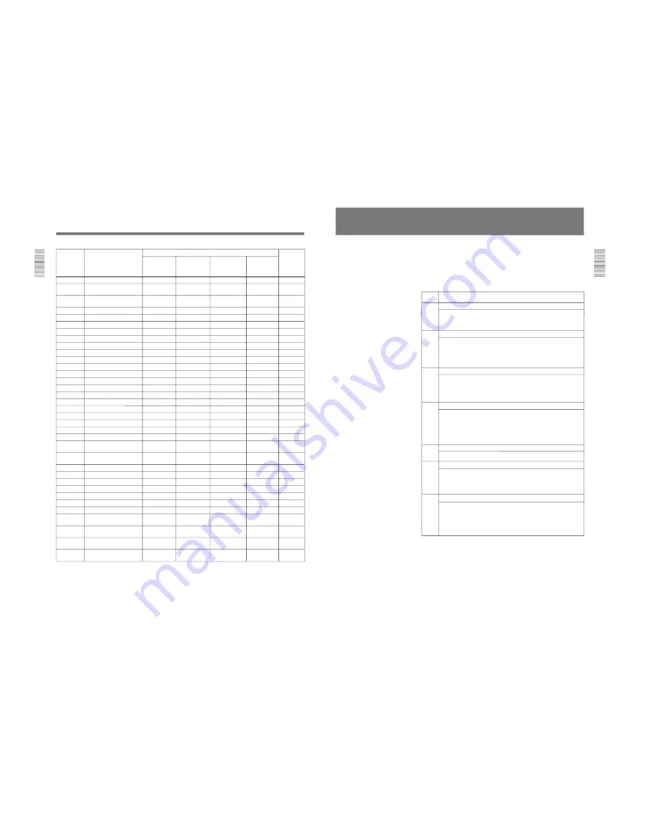
2300-2307
Two-picture slide
0
8
0
8
A-47
2320-2329
Two-picture slide,
0
10
0
10
A-47
2D rotation
2340-2357
Two-picture ro
0
18
0
18
A-48
Co Slide
2360-2375
Two-picture intersect
0
12
0
12
A-49
2380-2395
Two-picture box
0
16
0
16
A-50
2400-2419
Two-picture brick
0
18
0
18
A-51
2420-2437
Two-picture brick (flip type)
0
18
0
18
A-52
2470-2473
Split 3D rotation
0
4
0
4
A-52
2480-2499
Masked flip
0
20
0
20
A-53
2500-2519
2ch picture-in-picture
0
20
0
20
A-54
2520-2534
2ch picture-in-picture
0
13
0
13
A-55
2550-2554
Two-picture page turn
0
5
0
5
A-55
2560-2564
Split page turn
0
5
0
5
A-56
2600-2625
3D split
0
0
10
10
A-56
2630-2633
3D split flip
0
0
4
4
A-57
2640-2651
Multi-cube
0
0
9
9
A-57
2660, 2661
Three-picture multi-cube
0
0
0
2
A-57
2690-2692
Special wipe
0
0
3
3
A-58
2700-2715
3D page turn
0
0
12
12
A-58
2720-2724
3D twist
0
0
5
5
A-58
2730-2739
3D box twist
0
0
10
10
A-59
2740-2752
3D modeling effect
0
0
4
4
A-59
2800-2805
3D beveled edge,
0
0
6
6
A-60
Picture-in-picture
2810-2813
3D modeled edge,
0
0
4
4
A-60
Picture-in-picture
2820-2827
3D cube, 3D brick
0
0
8
8
A-60
2830-2833
3D cube
0
0
0
4
A-60
2840-2845
3D cylinder, Sphere, Heart
0
0
6
6
A-61
2850-2857
3D wave, 3D flag
0
0
8
8
A-61
2860, 2861
Kaleidoscope
0
0
2
2
A-61
2865, 2866
3D crystal, Mirror cube
0
0
2
2
A-61
2870-2881
3D object effect
0
0
9
9
A-62
9000-9009
Linear user program
10
10
10
10
4-4
(transition)
9100-9109
Linear user program
10
10
10
10
4-4
(animation)
9200-9209
Nonlinear user program
10
10
10
10
4-4
(transition)
9300-9309
Nonlinear user program
10
10
10
10
4-4
(animation)
Pattern No. Types of effects
The number of available patterns
Reference
page no.
Varieties in
standard
configuration
Varieties with
BKDF-711
installed
Varieties with
BKDF-712
installed
Varieties with
BKDF-711
and 712
installed
Effect Type List
Appendixes
Appendixes
A-5
Effect Control Parameter List
You can change effect pattern parameters by using the
pattern adjustment knobs, joystick, and Z-knob on the
control panel.
F1 to F5: Menu page 1
F6 to F10: Menu page 2
F11 to F15: Menu page 3
X/Y: Joystick
Z: Z-knob
Effect control parameters
1010
1011
1015
to
1018
User mosaic
1040
1043
1046
1050
1055
to
1058
Pattern
No.
Effect type and adjustable parameters
F1: Size of a mosaic cell (Size = 0 to 100)
F2: Aspect ratio of a mosaic cell (Aspect = Wider to taller)
F3: Softness (Soft = 0 to 100)
F5 : Type of cell (TYPE = FLAT, GLASS 1 to GLASS 4)
Pattern mosaic
F1: Size of a mosaic cell (Size = 0 to 100)
F2: Aspect ratio of a mosaic cell (Aspect = Wider to taller)
F3: Softness (Soft = 0 to 100)
F4: Aspect ratio of the mask area (MskAsp = Wider to taller)
F5: Type of cell (TYPE = FLAT, GLASS 1 to GLASS 4)
Y&C modify
F1: Degree of luminance masking (PstSol = OFF, LEVEL 1 to LEVEL 7)
Y&C modify
F1: Degree of luminance masking (Poster = OFF, LEVEL 1 to LEVEL 7)
F2: Positive/negative selection (VIDEO = NORMAL/NEGA/MONO/
MN+NEG)
F3: Softness (Soft = 0 to 100)
Y&C modify
F1: Degree of luminance masking (Poster = OFF, LEVEL 1 to LEVEL 7
F2: Positive/negative selection (VIDEO = NORMAL/NEGA/MONO/
MN+NEG)
F3: Softness (Soft = 0 to 100)
F4: Aspect ratio of the mask area (MskAsp = Wider to taller)
0017
0018
Wipe
F2: Rotation angle (Angle = 0 to 99)
F3: Rotation speed (Rot = 0 to 100)
F4: Auto center (CENTER = AUTO/FIX)
0021
to
0029
0034
to
0039
Wipe
F1: Pattern aspect ratio (Aspect = Taller to wider)
F2: Rotation angle (Angle = 0 to 99)
F3: Rotation speed (Rot = 0 to 100)
F4: Auto center (CENTER = AUTO/FIX)
(continued)
Содержание BKDF-701
Страница 5: ......
Страница 7: ......
Страница 113: ...1 106 DFS 700 700P Sony Corporation Printed in Japan ...


