2-7 (E)
BDX-N1000
Preparation
1.
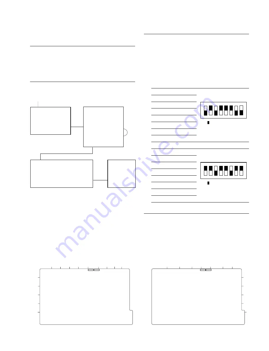
Connect the equipment.
2.
Set the switches S602 (F-1, E-1) and S603 (F-1, E-1)
on the IF-694 board as shown below.
n
Set the switches in the state of power-off, and after
settings are changed, turn the power-on.
S602
S602-1: OFF
S602-2 : ON
S602-3 : OFF
S602-4 : ON
S602-5 : ON
S602-6 : ON
S602-7: OFF
S602-8 : OFF
S603
S603-1 : ON
S603-2 : ON
S603-3 : OFF
S603-4 : ON
S603-5 : ON
S603-6 : OFF
S603-7 : ON
S603-8 : ON
Check procedures
1.
Output the MPEG TS (Transport Stream) from the
BDX-E1000 by the video bit rate of 15 Mbps or less.
2.
Observe the ANALOG VIDEO output of the BDX-
D1000 on a video monitor to check that the video
image does not have errors.
3.
After the check is completed, turn all switches of S602
and S603 on the IF-694 board to ON position.
< Serial No. 10001 to 10843 >
IF-694 board (A side)
VIDEO signal
VIDEO
INPUT
BIT STREAM
OUTPUT
MPEG
BIT STREAM
INPUT
MPEG
BIT STREAM
OUTPUT
ATM Tx
ATM Rx
BDX-N1000
BDX-E1000
BIT STREAM INPUT
DVB-ASI
ANALOG VIDEO
OUTPUT
BDX-D1000
Video monitor
(
*
)
2-3. BDKP-N1003/N1004 Installation
ON
1
2
3
4
5
6
7
8
( indicates the switch
lever position.)
ON
1
2
3
4
5
6
7
8
( indicates the switch
lever position.)
2. Picture check
Equipment required
.
MPEG encoder unit, BDX-E1000
.
MPEG decoder unit, BDX-D1000
.
Video monitor (Sony BVM series or equivalent)
Connection
(
*
) 75
Z
coaxial cable
A
B
C
D
E
G
F
H
1
2
3
4
5
6
S602
S603
< Serial No. 20001 and Higher >
IF-694 board (A side)
A
B
C
D
E
G
F
H
J
K
1
2
3
4
5
6
S602
S603
Suffix : -12
Suffix : -11


