


15
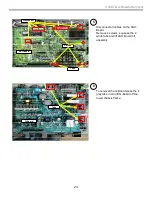
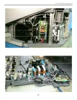
6. Q-Box & PD-Board Removal
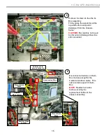
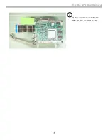
Access & Removal of Q-Box & PD-Board (cont.)
(Digital Module Block DMB )
5
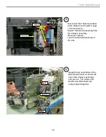
Remove 6 screws to free the Q -
Box assembly.
Firmly grasp the assembly at the
top and bottom and pull to
dislodge it from the chassis
frame.
CAUTION:
Be carefully not to pull
too far out and damage the wires
still connected.
Screws
Peel Back tape
custom
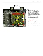
6
Disconnect all cables on the Q-
Box module except for the
CableCard ribbon cable. This
cable remains apart of the Q -
Box.
NOTE:
Reattach all wires
before securing the
replacement Q-Box to the
chassis assembly.
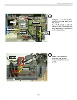
Disconnected
Wires
Disconnected Wires
Unscrew
RF-connector
Disconnected
Wires
Pull wire out to
access connector
Содержание 2005 SXRD KDS-R50XBR1
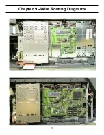
Страница 26: ...24 Chapter 9 Wire Routing Diagrams Wire Routing Diagrams ...
Страница 27: ...25 9 Wire Routing Diagrams Wire Routing Diagrams cont ...
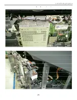
Страница 28: ...26 9 Wire Routing Diagrams Wire Routing Diagrams cont ...
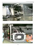
Страница 29: ...27 9 Wire Routing Diagrams Wire Routing Diagrams cont ...
Страница 30: ...28 9 Wire Routing Diagrams Wire Routing Diagrams cont ...