SN8P2711A
8-Bit Micro-Controller
SONiX TECHNOLOGY CO., LTD
Page 48
Version 0.1
4
4
4
SYSTEM CLOCK
4.1 OVERVIEW
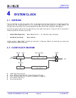
The micro-controller is a dual clock system. There are high-speed clock and low-speed clock. The high-speed clock is
generated from the external oscillator circuit or on-chip 16MHz high-speed RC oscillator circuit (IHRC 16MHz). The
low-speed clock is generated from on-chip low-speed RC oscillator circuit (ILRC 16KHz @3V, 32KHz @5V).
Both the high-speed clock and the low-speed clock can be system clock (Fosc). The system clock in slow mode is
divided by 4 to be the instruction cycle (Fcpu).
)
Normal Mode (High Clock):
Fcpu = Fhosc / N
, N = 1 ~ 16, Select N by Fcpu code option.
)
Slow Mode (Low Clock):
Fcpu = Flosc/4.
SONIX provides a
“Noise Filter”
controlled by code option. In high noisy situation, the noise filter can isolate noise
outside and protect system works well.
4.2 CLOCK BLOCK DIAGRAM
Fhosc.
Fcpu = Fhosc/1 ~ Fhosc/16
Flosc.
Fcpu = Flosc/4
CPUM[1:0]
XIN
XOUT
STPHX
HOSC
Fcpu Code Option
Fosc
Fosc
CLKMD
Fcpu
z
HOSC: High_Clk code option.
z
Fhosc: External high-speed clock / Internal high-speed RC clock.
z
Flosc: Internal low-speed RC clock (about 16KHz@3V, 32KHz@5V).
z
Fosc: System clock source.
z
Fcpu: Instruction cycle.

