SN8P2711A
8-Bit Micro-Controller
SONiX TECHNOLOGY CO., LTD
Page 104
Version 0.1
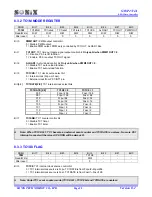
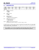
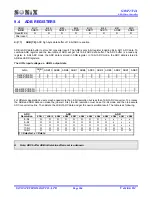
9.2 ADM
REGISTER
0B1H
Bit 7
Bit 6
Bit 5
Bit 4
Bit 3
Bit 2
Bit 1
Bit 0
ADM
ADENB ADS EOC GCHS
-
CHS2 CHS1 CHS0
Read/Write R/W
R/W
R/W R/W - R/W R/W R/W
After
reset
0 0 0 0 - 0 0 0
Bit 7
ADENB:
ADC control bit.
0 = Disable.
1 = Enable.
Bit 6
ADS:
ADC start bit.
0 = Stop.
1 = Starting.
Bit 5
EOC:
ADC status bit.
0 = Progressing.
1 = End of converting and reset ADS bit.
Bit 4
GCHS:
Global channel select bit.
0 = Disable AIN channel.
1 = Enable AIN channel.
Bit[2:0]
CHS[2:0]:
ADC input channels select bit.
000 = AIN0, 001 = AIN1, 010 = AIN2, 011 = AIN3, 100 = AIN4, 101 = AIN5.
The AIN5 is internal 1/4 VDD input channel. There is no any input pin from outside. AIN5 can be a good battery
detector for battery system. To select appropriate internal VREFH level and compare value, a high performance and
cheaper low battery detector is built in the system.
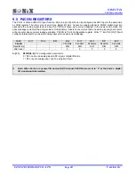
Note: If ADENB = 1, users should set P4.n/AINn as input mode without pull-up. System doesn’t set
automatically. If P4CON.n is set, the P4.n/AINn’s digital I/O function including pull-up is isolated.

