


3
SYSTEM ORIENTATION
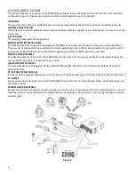
This section provides an overview of the SON200 Series Digital Intercom System and an introduction to its individual
components. Figure 2 shows a typical system. Refer to this diagram for each component.
INTERCOM
The main control unit for the SON200 Series Intercom System which contains all the controls and interface circuitry.
WIRELESS BASE STATION
A Module which provides wireless communications between wireless headset users, belt pack users, and intercom and
radio users.
2-WAY RADIO
The existing 2-way radio in the apparatus.
MOBILE RADIO INTERFACE CABLE
Provides the interface connections between the SON200 Series Intercom Unit and the 2-way radio in the apparatus.
There are many cable assemblies available; the cable needed depends on the make and model of your radio. Contact
your local Sonetics Dealer for more information regarding an Interface Cable specific to your radio.
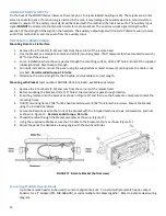
POWER CABLE ASSEMBLY
Provides the power connections for the SON200 Series Intercom Unit. The power connections should be made at the
same place as the power connections for your radio.
HM-10 HEADSET MODULES
The wired headset will be plugged into the Headset Module (HM-10) which is the standard module for headset-to-
system interface.
PP-20 PUMP PANEL MODULE
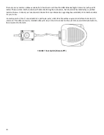
A water-resistant Headset Module used on the exterior of the apparatus (e.g. at the Pump Panel, at the tail-board, etc.).
CA CABLES
Six-conductor flat cable which connects the SON200 Series Intercom Unit to the Wireless Bases, Headset Module, and
the Remote Head.
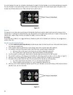
REMOTE HEAD INTERCOMS
Remote Head Intercoms can be connected to the main control unit to control the unit from a remote location. Up to 5
remotes heads can be connected to the digital intercom by utilizing an RJ-12 splitter or by splicing into the 6 conductor
modular cable.
Figure 2