


15
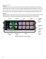
AUXILIARY INPUT & OUTPUT
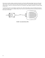
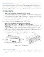
On the back of the SON200 Series Intercom, there may be 1 to 4 jacks labeled Aux
(Figure 15). These jacks are 3.5 mm
stereo (conductor) jacks. If a mono plug is inserted in this jack, it may damage the auxiliary device. A mono-to-stereo
adapter is required. The auxiliary input signal will be mixed with the radio and the intercom audio. The auxiliary input
signal
CANNOT
be directed to the transmit circuits for radio broadcast. The auxiliary output signal
strength will be
exactly 1/2 the strength of the signal in the headsets. The auxiliary output signal will consist of intercom audio, receive
audio from radios A & B, and any audio from the auxiliary input.
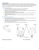
INSTALLING A REMOTE HEAD:
Mounting Flush to a Flat Surface
1.
Remove the 4 Torx bolts (T-10) and nuts from the corners of the remote head
2.
Use the bracket as a template to mark and drill (4) mounting holes: 7/64" diameter for sheet metal screws or 5/
32" for machine screws
3.
For an installation where the wire passes through the mounting surface, drill a 3/8" hole and install the supplied
rubber grommet. Pass the wire through.
4.
For inside installation, mount the panel using the supplied sheet metal screws (4), making sure the cable is not
pinched.
Recommended torque: 10 in-lbs.
5.
Determine the correct length for the CA cable, and cut cable to correct length.
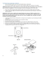
Mounting with Bracket
(part number 108-0303-00 not included - available separately)
1.
Remove the 4 Torx bolts (T-10) and nuts from the corners of the remote head
2.
Before mounting the bracket, drill a 3/4" hole at the desired wire pass-through location.
3.
Snap the grommet into the bracket as shown in (Figure 17) and then use the bracket as a template to mark the
mounting holes.
4.
Drill (4) mounting holes: 7/64" for #6 sheet metal screws or 9/64" for #6 machine screws. Mount the bracket
using the included hardware
5.
Secure the Remote Head to the front of the bracket with the included machine screws, split washers, and nuts
as shown in Figure 17.
Recommended torque: 10 in-lbs.
6.
Thread the cable through the bracket assembly as shown in (Figure 17).
7.
Using the supplied cable ties secure the CA Cable to the bracket anchors as shown (Figure 17).
8.
Adjust the panel to a desirable viewing angle with the two hand knobs.
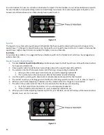
FIGURE 17: Remote Bracket (bottom view)
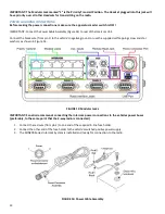
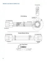
Connecting Multiple Remote Heads
Up to five remote heads can be used to control a digital intercom. To install multiple remote heads, contact
Sonetics for a ‘Y’ adapter (PN: 108-0066-00), or splice multiple CA Cables together. Refer to Remote Head wiring
diagram.