Initial Issue
Issue Date 25/06/2010
User Manual: 8142/8182 Transceivers
12 Installation
Page
7of 13
10.
Fit the transceiver cable to the transceiver a master pin makes sure the plug is located
correctly.
11.
Hand tighten the locking sleeve on the transceiver cable (Ref Photo 5).
12.
Install applicable lifting equipment to the pole.
13.
Get the crane operator to slowly lift the lifting equipment until the weight of the pole unit
shows on the display of the control facia.
NOTE:
Never let the weight of the pole be supported on the transceiver front face.
14.
Move the pole into position over the transceiver and slowly lower into position.
15.
Lift the transceiver up to the pole.
16.
The adapter and flange should maintain the alignment of the transceivers lubber line
mark with the ship’s lubber line. The Sonardyne adapter has provision for two dowel pins.
NOTE
Alignment should be maintained to within 1 degree.
17.
Secure the transceiver to the pole using the bolts, insulation washers, dual washers and
spring washers from the installation kit.
18.
Hand-tighten with an Allen key to approximately 5Nm.
19.
Remove the red protective cover from the transceiver before deployment.
20.
The pole will normally have a number of flanges with a compliant outer edge that contacts
the inside wall of the tube.
21.
The pole should not change its vertical alignment with respect to the ship by more than
0.5 degrees.
22.
For deep water applications, and if Vertical Reference Units (VRU) are available, then a
closer tolerance can be achieved.
2.2
TRANSCEIVER INTERCONNECTIONS
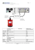
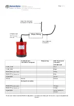
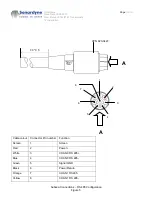
All transceiver interconnections (Ref.
Fig 1 to 5
) for cable part numbers see recommended parts list.
The terminal strip and junction box supplied by customer.
Содержание 8142-000-01
Страница 100: ......


