background image

LEVIXO 30/50 230V RTS

EN

5

Copyright

©

 2017 SOMFY ACTIVITES SA. All rights reserved. 

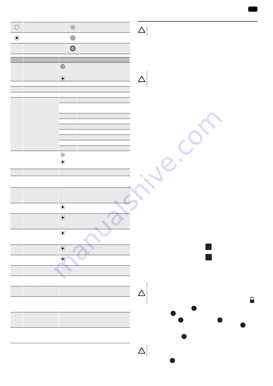
2.5. Description of the circuit board - Fig. 3

Off

Slow flashing

Permanently lit

Rapid flashing

Very rapid flashing

No.

Description

Comments

1

POWER indicator

 :  Electronic fault (motor thermal cut-

out, etc.)

 : Motor on

2

SET indicator

Not used

3

SET button

Not used

4

TIME potentiometer Setting of the automatic timed close

5

Dipswitches

1 - 2

Not used

3

Motor direction of rotation: 

installation on left or right

4

Auxiliary output: Lighting

5

Lighting time delay

6

Wire input operating modes

7 - 8 - 9 Motorisation operating modes

10

Safety edge autotest

11

Orange light warning

12

Cell autotest during closing

6

PROG indicator light

 : Radio reception
 :  Awaiting memorisation of a radio 

control point

7

PROG button

Radio control points memorised/cleared

8

Removable terminal 

block

Terminals 9 to 20: Wiring the accessories
Terminals 21 to 23: Wiring the end limits

9

Non-removable 

terminal block (ter-

minals 24 and 25)

Aerial wiring

10

Safety edge input 

indicator light

 :  Fault or activation of the safety edge

11

Cell active during 

closing input indica-

tor light

 :  Fault or photoelectric cells obstructed

12

"Cell active during 

opening input" 

indicator light

 :  Fault or photoelectric cells obstructed

13

Total control input 

indicator

 :  Input activated

14

Pedestrian control 

input indicator

 :  Input activated

15

250 V 3.15 AF fuse

Protection of the motor and the 230 V 

orange light

16

250V 100 mAT fuse Surge protection for the 24 V accessories 

outputs

17

250V 315 mAT fuse Short circuit protection for the 24 V acces-

sories outputs

18

Non-removable 

terminal block 

(terminals 1 to 3)

230V power supply wiring

19

Removable terminal 

block (terminals 4 

to 6)

Motor wiring (wired in the factory)

20

Removable terminal 

block (terminals 7 

and 8)

Wiring for the orange light

3. INSTALLATION

Attention

Check that the ground is level.

͉

͉

 The barrier can be installed either directly on the ground or using the 

mounting plate provided (recommended for easier levelling).
The barrier is supplied for left-hand mounting.
The door of the housing must be facing inside the property.

3.1. Preparing the base

Attention

Before opening the door of the housing, ensure that the spring is 

released by moving the boom to the vertical position.

3.1.1. Foundations with a base plate (optional) and con-

crete foundation - Fig. 4

1)  Make a hole in the base suitable for the type of terrain.
2)  Use several ducts to route the electrical cables.
3)  Place the 4 bolts supplied with the base plate in the final position with 

the thread of the bolt facing upwards and weld the heads of the 4 bolts 

to the base. Protect the welds with an anti-rust product.

4)  Position the plate so that it protrudes from the ground by approximate-

ly 20 mm.

5)  Fill the base with concrete, using a spirit level to check the position of 

the plate in both directions, and leave the cement to harden.

3.1.2. Foundations without base plate Fig. 5

1)  Place the housing on the ground.
2)  Mark the mounting holes.
3)  Remove the housing.
4)  Drill the mounting holes.
5)  Insert plugs (not provided) in the mounting holes.

͉

͉

 The top surface of the housing is angled slightly to prevent rain water 

from collecting. Use a side surface to check that the housing is level.

3.2. Mounting the housing - Fig. 6

Secure the housing using M12 nuts.

3.3. Identifying the barrier’s mounting direction - 

Fig. 7

Standing in the middle of the gap and facing the outside: 

•   if the housing is on the left (Fig. 7 

A

), refer directly to the boom 

mounting section.

•   if the housing is on the right (Fig. 7 

B

), refer to the following sec-

tion for right-hand mounting.

3.4. Mounting on the right (opposite of factory 

mounting) - Fig. 8

Attention

Before performing any work in the housing, ensure that the spring 

is released by moving the boom to the vertical position.
Lock the boom by turning the key to the padlock closed position  .

1)  Slacken the spring tensioner 

1

 completely using a Ø19 spanner until 

the bolt and nut 

2

 securing the base of the housing can be removed.

2)   Remove the bracket 

3

 and loosen the bolt 

4

 using a Ø19 spanner 

(with a tightening offset of at least 40 mm) until the lever 

5

 begins 

to rotate.

3)  Pull and turn the lever 

5

 180°. Only one position is possible at 180°, 

and is indicated by a notch.

Attention

Be sure not to damage the end limit contacts.

4)  Tighten the bolt 

4

 which immobilises the lever using a torque wrench 

set to a torque of approximately 80 Nm.

Содержание Levixo 30

Страница 1: ...Levixo 30 50 230V RTS Manuel d installation Installation instructions Montaj kılavuzu FR EN EN TR FA AR ...

Страница 2: ...troduction 2 1 3 Vérifications préliminaires 3 1 4 Installation électrique 3 1 5 Précautions de manutention 3 1 6 Précautions vestimentaires 3 1 7 Consignes de sécurité relatives à l installation 3 1 8 Consignes de sécurité relatives à l utilisation 3 1 9 Consignes de sécurité relatives à la maintenance 4 1 10 À propos des piles 4 1 11 Recyclage et mise au rebut 4 1 12 Réglementation 4 1 13 Assist...

Страница 3: ... Précautions vestimentaires Enlever tous bijoux bracelet chaîne ou autres lors de l installation Pour les opérations de manipulation de perçage et de soudure porter les protections adéquates lunettes spéciales gants casque antibruit etc 1 7 Consignes de sécurité relatives à l installation DANGER Nepasraccorderlamotorisationàunesourced alimentation avant d avoir terminé l installation DANGER L inst...

Страница 4: ... ni les jeter dans le feu ni les recharger Il y a risque d explosion 1 11 Recyclage et mise au rebut Ne pas jeter les piles usagées des télécommandes avec les déchets ménagers Les déposer à un point de collecte dédié pour leur recyclage Ne pas jeter la motorisation hors d usage avec les déchets ménagers Faire reprendre la motorisation par son distributeur ou utiliser les moyens de collecte sélecti...

Страница 5: ...gauche La porte du caisson doit être orientée vers l intérieur de la propriété 3 1 Préparation des fondations Attention Avant toute ouverture de la porte du caisson s assurer de la détente du ressort en amenant la lisse en position verticale 3 1 1 Fondations avec plaque d assise en option et fondation béton Fig 4 1 Creuser une fondation adaptée au type de terrain 2 Prévoir plusieurs conduites pour...

Страница 6: ... 3 7 2 Réglage des fins de course pour un montage droite Fig 13 3 8 Equilibrage de la lisse Fig 14 Attention Avant toute ouverture de la porte du caisson s assurer de la détente du ressort en amenant la lisse en position verticale 1 Déverrouiller la lisse position cadenas ouvert 2 Accompagner la lisse jusqu à son point d équilibre 3 Desserrer le contre écrou 1 4 Tendre ou détendre le ressort 2 jus...

Страница 7: ...ase 3 Neutre 4 M Moteur 5 6 7 Flash Sortie feu orange ou éclairage de zone 230V 60W max Gestion du clignotement par le feu orange 8 9 Aux Sortie auxiliaire contact sec Choix éclairage avec dipswitch 4 10 11 Test Sortie test sécurité Autotest de la barre palpeuse et des cellules actives en fermeture 12 24 V Alimentation 24V accessoires 315 mA max pour l ensemble des accessoires sur toutes les sorti...

Страница 8: ...la temporisation la barrière se fermera à l issue de la nouvelle temporisation Si un obstacle est présent dans la zone de détection des cellules la barrière ne se ferme pas Elle se fermera une fois l obstacle enlevé DIP SW 7 DIP SW 8 DIP SW 9 Réglage Automatique blocage cellule ON OFF OFF En mode automatique la position finale de la barrière sera toujours la position fermée Le fonctionnement en mo...

Страница 9: ...TIQUES TECHNIQUES Barrière Alimentation secteur 220 230 Vac 50 60 Hz Puissance absorbée 300 W Couple maximum 85 Nm Levixo 30 250 Nm Levixo 50 Fins de course Électriques intégrées et réglables Détection d obstacle Barre palpeuse active avec auto test Déverrouillage Clé individuelle Temps d ouverture 4 s Levixo 30 8 s Levixo 50 Longueur de lisse maximum 3 m sans accessoires Levixo 30 5 m sans access...

Страница 10: ... 2 1 3 Preliminary checks 3 1 4 Electrical installation 3 1 5 Handling precautions 3 1 6 Clothing precautions 3 1 7 Safety instructions relating to installation 3 1 8 Safety instructions relating to use 3 1 9 Safety instructions relating to maintenance 4 1 10 About the batteries 4 1 11 Recycling and disposal 4 1 12 Regulations 4 1 13 Assistance 4 2 Product description 4 2 1 Scope of application 4 ...

Страница 11: ...priate protection special glasses gloves ear protection etc 1 7 Safety instructions relating to installation DANGER Do not connect the motorisation to a power source before installation is complete DANGER It is mandatory to install an active safety edge with autotest function in order for the installation to be compliant WARNING Ensure that any danger zones crushing cutting trapping between the mo...

Страница 12: ...cial waste collection services 1 12 Regulations Somfy declares that when used in accordance with these in structions the product described in these instructions complies with the essential requirements of the applicable European Di rectives and in particular Machinery Directive 2006 42 EC and Radio Equipment Directive 2014 53 EU The full text of the EC declaration of conformity is available at the...

Страница 13: ... inside the property 3 1 Preparing the base Attention Before opening the door of the housing ensure that the spring is released by moving the boom to the vertical position 3 1 1 Foundations with a base plate optional and con crete foundation Fig 4 1 Make a hole in the base suitable for the type of terrain 2 Use several ducts to route the electrical cables 3 Place the 4 bolts supplied with the base...

Страница 14: ...ng ensure that the spring is released by moving the boom to the vertical position 1 Unlock the boom padlock open position 2 Guide the boom until it is balanced 3 Loosen the locknut 1 4 Tension or slacken the spring 2 until the boom remains balanced at approximately 45 if the boom seems to open slacken the spring by moving the tie rod if the boom seems to close tension the spring by moving the tie ...

Страница 15: ...ash Orange light or zone lighting output max 230V 60W Flashing managed by the orange light 8 9 Aux Auxiliary output dry contact Choice of lighting using dipswitch 4 10 11 Test Safety test output Safe corner autotest and active cells closed 12 24 V 24V accessories power supply 315 mA max for all accesso ries on all outputs 13 0 V 14 SE Dry contact Safety edge Active during closing and opening 15 Sh...

Страница 16: ... close when the new time delay has elapsed If there is an obstacle in the cells detection zone the barrier will not close It will close once the obstacle is removed DIP SW 7 DIP SW 8 DIP SW 9 Setting Automatic cell blocking ON OFF OFF In automatic mode the final position of the barrier will always be the closed position Operation in automatic closing mode is only au thorised if the photoelectric c...

Страница 17: ...itch no 10 to ON 5 Test the safety edge 10 TECHNICAL DATA Barrier Power supply 220 230 Vac 50 60 Hz Power consumption 300 W Maximum torque 85 Nm Levixo 30 250 Nm Levixo 50 End limits Integrated and adjustable electrical Obstacle detection Safety edge active with autotest Unlocking Individual key Opening time 4 s Levixo 30 8 s Levixo 50 Maximum boom length 3 m without accessories Levixo 30 5 m with...

Страница 18: ...arı 2 1 2 Giriş 2 1 3 Ön kontroller 3 1 4 Elektrik montajı 3 1 5 Taşıma önlemleri 3 1 6 Giysilerle ilgili önlemler 3 1 7 Montajla ilgili güvenlik talimatları 3 1 8 Kullanımla ilgili güvenlik talimatları 3 1 9 Bakımla ilgili güvenlik talimatları 4 1 10 Piller hakkında 4 1 11 Geri dönüşüm ve hurdaya çıkarma 4 1 12 Yönetmelik 4 1 13 Destek 4 2 Ürün tanımı 4 2 1 Uygulama alanı 4 2 2 Ölçüler Şekil 1 4 ...

Страница 19: ...erle ilgili önlemler Montajsırasındatümtakıların bilezik zincir kolyeveyadiğerleri çıka rılmasıgerekir Montaj sırasında delik açma kaynaklama veya benzeri işlemler yapı lırken gerekli koruma önlemlerini özel gözlükler koruyucu eldiven gürültüönleyicikaskvb mutlakaalınız 1 7 Montajla ilgili güvenlik talimatları TEHLIKE Montaj bitmeden kesinlikle motoru bir besleme kaynağına bağ lanmayınız TEHLIKE M...

Страница 20: ...erçekleşmesihalinde vakitgeçirmedenbirdoktorabaşvurunuzveyahastaneyegidiniz Pillerin kısa devre yapmamasına ateşe atılmamasına veya şarj edilmemesinedikkatediniz Patlamatehlikesivardır 1 11 Geri dönüşüm ve hurdaya çıkarma Uzaktan kumandaların boşalmış pillerini evsel atıklarla birlikte çöpe atmayınız Geri dönüşüm için bunları yetkili kuruluşlarateslimediniz Kullanım ömrünü tamamlamış motoru evsel ...

Страница 21: ...ye ayarlanmasını kolaylaştır masınedeniyleönerilir Bariyer soltarafamonteedilecekşekildeteslimedilir Kasanın kapısıürünün içinedoğruyönlendirilmişolmalıdır 3 1 Temellerin hazırlanması Dikkat Kasa kapısının her açılmasından önce bariyer kolunu dikey konuma getirerek yayın gerginliğinin azalmasını sağlayınız 3 1 1 Dayanaklevhasıyla opsiyonelolarak kasasabitleme ve beton temel Şekil 4 1 Zemintipineuy...

Страница 22: ... gerginliğinin azalmasını sağlayınız 1 Bariyerkolununkilidiniaçınız asmalıkilitaçık konumu 2 Dengenoktasınakadarsürgüyeeşlik ediniz 3 Karşısomunugevşetiniz 1 4 Sürgü 45 de dengede kalacak şekilde 2 yayı geriniz ya da serbest bıra kınız Bariyer kolu açılmaya eğilim gösterirse gergi çubuğuna işlem yaparak yayıgevşetiniz Bariyer kolu kapanmaya eğilim gösterirse gergi çubuğuna işlem yapa rak yayıgerin...

Страница 23: ...7 Flaş Turuncu flaşör veya bölge aydınlatma çıkışı 230V 60W maks Turuncu flaşörün yanıp sönme kumandası 8 9 Yardımcı Yardımcı çıkışı kuru kontak Aydınlatma seçimi dipswitch 4 ile yapılır 10 11 Test Güvenlik testi çıkışı Kapanma sırasında engel algılayıcının ve aktif fotosel lerin otomatik testi Uçlar Bağlantı Tanım 12 24 V 24 V aksesuar beslemesi Tüm çıkışlarda aksesuar grubu için maks 315 mA 13 0...

Страница 24: ...niden başlatır bariyer yeni zamanlamaya göre kapanacaktır Fotosellerin algılama alanında bir engel mevcut sa kapı kapanmaz Engel kalktığında kapanır DIP SW 7 DIP SW 8 DIP SW 9 Ayar Otomatik fotoselin engellenmesi ON OFF OFF Otomatik modda bariyerin son konumu her zaman kapalı konum olacaktır Otomatik kapanma modunda çalışmaya sadece otomatik test özellikli fotoseller takılı olduğunda izin verilir ...

Страница 25: ...iniz 5 engelalgılayıcıyıtestediniz 10 TEKNIK ÖZELLIKLER Bariyer Şebeke beslemesi 220 230 Vac 50 60 Hz Çekilen güç 300 W Maksimum tork 85 Nm Levixo 30 250 Nm Levixo 50 Çevrim sonları Entegre ve düzenlenebilir elektrik Engel algılama Otomatik testli engel algılayıcı aktif Kilit açma Kişisel anahtar Açılma süresi 4 s Levixo 30 8 s Levixo 50 Maksimum bariyer kolu uzunluğu 3 m aksesuarsız Levixo 30 5 m...

Страница 26: ...لبه حسگر 10 10 فنی مشخصات اهبند ر ورودی ولتاژ 220 230 Vac 50 60 Hz مرصفی توان 300 W گشتاور حداکرث Levixo 50 250 Nm Levixo 30 85 Nm ها ت حرک انتهای تنظیم قابل و شده تعبیه الکرتیکی مانع تشخیص خودکار تست با فعال لبه حسگر کردن فعال ا ز مج کلید شدن باز زمان Levixo 50 ثانیه 8 Levixo 30 ثانیه 4 بازو طول حداکرث Levixo 30 جانبی ات ز تجهی بدون مرت 3 Levixo 50 جانبی ات ز تجهی بدون مرت 5 استفاده هوایی و آب ای...

Страница 27: ...ی زمان ابتدای از اهبند ر دهد ی م شود ی م داشته وجود ها ل سلو تشخیص محدوده در مانعی اگر برداشته مانع وقتی فقط شود ی من بسته اهبند ر باشد شود ی م بسته درب شود DIP SW 7 DIP SW 8 DIP SW 9 تنظیم سلول کردن متوقف اتوماتیک ON OFF OFF همیشه اهبند ر نهایی موقعیت اتوماتیک حالت در است بسته موقعیت وقتی فقط اتوماتیک شدن بسته حالت در عملکرد تست با فتوالکرتیک های ل سلو که است میرس باشند شده نصب خودکار اگر ها ل سل...

Страница 28: ...طه روشنایی یا 230V 60W حداکرث اغ ر چ توسط زدن چشمک کنرتل نارنجی 8 9 Aux اتصال کمکی خروجی خشک دیپ با روشنایی انتخاب 4 سوئیچ 10 11 Test ایمنی تست خروجی و لبه حسگر خودکار تست شدن بسته در فعال های ل سلو 12 24 V ولت 24 تغذیه جانبی ات ز تجهی مجموعه ای ر ب 315 mA حداکرث متام روی جانبی ات ز تجهی ها ی خروج 13 0 V ها ه پای اتصاالت رشح 14 SE خشک اتصال لبه حسگر و شدن بسته هنگام در فعال شدن باز 15 عمومی 16 Sec...

Страница 29: ...3 3 3 3 13 شکل است ر سمت در نصب ای ر ب ت حرک انتهای تنظیم 3 3 3 3 14 شکل بازو کردن متعادل توجه موقعیت در بازو دادن حرکت با باید محفظه درب کردن باز از قبل شوید مطمنئ فرن بودن اد ز آ از عمودی 1 1 باز قفل موقعیت کنید اد ز آ ا ر بازو 2 2 کنید اهی ر هم توازن نقطه تا ا ر بازو 3 3 کنید باز ا ر 1 کن قفل مهره پیچ 4 4 متعادل حالت در درجه 45 در بازو که حدی تا کنید فرشده یا اد ز آ ا ر 2 فرن مباند کنید اد ز آ ...

Страница 30: ...تحویل چپ سمت در نصب ای ر ب اهبند ر باشد داشته ار ر ق ملک داخل سمت به باید محفظه درب 3 3 3 3 فونداسیون سازی آماده توجه موقعیت در بازو دادن حرکت با باید محفظه درب کردن باز از قبل شوید مطمنئ فرن بودن اد ز آ از عمودی 3 3 3 3 3 3 و اختیاری نشیمنگاه صفحه اه ر هم به فونداسیون 4 شکل بتون فونداسیون 1 1 بکنید زمین خاک نوع با مطابق فونداسیون یک 2 2 بگیرید نظر در ها ل کاب عبور ای ر ب متعدد های ل کانا 3 3 رزوه...

Страница 31: ...ه آوری ع جم اکز ر م از یکی به نیاندازید دور خانگی دهید تحویل بازیافت منظور دور خانگی های ه زبال اه ر هم به ا ر شده خارج رده از موتور اکز ر م از یکی به یا آن کننده توزیع به ا ر موتور نیاندازید دهید تحویل ویژه آوری ع جم 1 1 1 1 ات ر مقر دفرتچه این در شده توصیف محصول دارد ی م اعالم سامفی وسیله بدین با گیرد ار ر ق استفاده مورد ها ل العم ر دستو این مطابق که هنگامی اهنام ر بخشنامه خصوص به اروپا اتحادیه ...

Страница 32: ...ز اب از نقل و حمل چرخ یک مثال ای ر ب 1 1 1 1 پوشش به مربوط های ط احتیا غیره و زنجیر دستبند کنید باز نصب هنگام را خود زیورآالت مناسب های ظ محاف از جوشکاری و کاری اخ ر سو رسیدگی عملیات ای ر ب غیره و صدا ضد گوشی دستکش مخصوص عینک کنید استفاده 1 1 1 1 نصب با مرتبط ایمنی های ل العم ر دستو خطر اری ر اضط باتری یا شهر برق به ا ر موتور نصب عملیات پایان از قبل نکنید وصل ا ر خطر فعال لبه حسگر نصب استانداردها ...

Страница 33: ... دستو 1 2 ایمنی مهم های العمل ر دستو هشدار 1 1 ۲ مقدمه 2 1 ۳ اولیه های ی بررس 3 1 3 الکرتیکی ات ز تجهی نصب 4 1 3 جایی ه جاب به مربوط های ط احتیا 5 1 3 پوشش به مربوط های ط احتیا 6 1 3 نصب با مرتبط ایمنی های ل العم ر دستو 7 1 3 نصب با مرتبط ایمنی های ل العم ر دستو 8 1 4 نگهداری با مرتبط ایمنی های ل العم ر دستو 9 1 4 ها ی باتر خصوص در 10 1 4 کردن خارج رده از و بازیافت 11 1 4 ات ر مقر 12 1 4 پشتیبانی ...

Страница 34: ... 10 الفنية املواصفات الحاجز الطاقة منبع هرتز 60 50 مرتدد تيار فولت 230 220 املستهلكة القدرة وات 300 للعزم األقىص الحد مرت نيوتن 250 Levixo 30 مرت نيوتن 85 Levixo 50 الطرفية الحدود للضبط قابلة و مدمجة كهربائية عائق اكتشاف ذايت اختبار مع فعال استشعار قضيب القفل تحرير فردي مفتاح الفتح زمن Levixo 50 ِ ثوان 8 Levixo 30 ِ ثوان 4 للعارضة طول أقىص بدون مرت 5 Levixo 30 ملحقات بدون مرت 3 Levixo 50 ملحقات ام...

Страница 35: ...ف التوقيت تشغيل عيد ُ ي الغلق توقيت أثناء الجديد التوقيت بعد الحاجز فإن الخاليا اكتشاف منطقة يف ما عائق وجود حالة يف العائق زوال عند وينغلق ينغلق ال الحاجز DIP SW 7 DIP SW 8 DIP SW 9 الضبط الخلية إيقاف تلقايئ ON OFF OFF دامئا للحاجز النهايئ الوضع سيكون التلقايئ الوضع يف املغلق الوضع تركيب تم إذا إال التلقايئ الغلق وضع يف بالتشغيل سمح ُ ي ال ذايت اختبار مع الكهروضوئية الخاليا مدخل كان إذا الخاليا أ...

Страница 36: ...لحتياطي املخرج ثانوي توصيل تبديل مفتاح عرب االضاءة اختيار 4 مزدوج 10 11 اختبار السالمة اختبار مخرج االستشعار لقضيب ذايت اختبار اإلغالق عند النشطة والخاليا 12 فولت 24 فولت 24 طاقة منبع ابع و للت إلجاميل أقىص بحد أمبري مليل 315 املخارج جميع عىل امللحقات 13 فولت 0 اف ر األط التوصيل الوصف 14 SE ثانوي توصيل استشعار قضيب الغلق وأثناء الفتح أثناء نشط 15 مشرتك 16 Sec Cell c ثانوي توصيل الغلق عند لة ّ ع مف...

Страница 37: ... 13 شکل اليمني جهة للرتكيب الطرفية الحدود ضبط 3 3 3 3 14 شکل العارضة موازنة تنبيه طريق عن الزنربك انبساط من التأكد يجب العلبة لباب فتح بأي القيام قبل الرأيس الوضع يف العارضة جعل 1 1 املفتوح القفل وضع العارضة قفل حرر 2 2 انها ز ات لنقطة تصل حتى العارضة افق ر 3 3 1 الحزقة ماسكة بفك فم 4 4 ً ا تقريب 45 اوية ز عند ان ز لالت العارضة تصل حتى 2 الزنربك شد أو بإرخاء قم الشدادة تحريك مع الزنربك شد تنفتح أن...

Страница 38: ...تثبيت لوح مع أو األرض عىل ً ة مبارش إما الحاجز تركيب ميكن املستوى ضبط لتسهيل باستخدامه اليسار جهة للرتكيب ُ ا ز جاه الحاجز تسليم يتم للبناية الداخلية للجهة العلبة باب توجيه يجب 3 3 3 3 األساسات تجهيز تنبيه طريق عن الزنربك انبساط من التأكد يجب العلبة لباب فتح بأي القيام قبل الرأيس الوضع يف العارضة جعل 3 3 3 3 3 3 واألساس اختياري القاعدة لوح مع األساسات 4 شكل الخرساين 1 1 األرض لنوعية ً ا مناسب ً ا ...

Страница 39: ...تخلص ال صة ّ مخص تجميع نقطة يف منها تخلص املنزلية املخلفات تدويرها إلعادة قم املنزلية ّفات ل املخ مع الخدمة خارج ك ِّ ر املح بإلقاء تقم ال االنتقائية الجمع وسائل استخدام أو ِّعه ز مو إىل ك ِّ ر املح بإعادة ف ّ رص الت تحت الحي يضعها التي 1 1 1 1 اللوائح تم إذا التعليامت هذه يف املوصوف املنتج أن Somfy رشكة تعلن األساسية املتطلبات مع يتوافق فإنه التعليامت لهذه ًا ق طب استخدامه 2006 42 EC اآلالت توجيه...

Страница 40: ...امل احتياطات عىل الحمولة ووزن وأبعاد شكل املالمئة التعامل وسائل استخدم نقل عربة املثال سبيل 1 1 1 1 باملالبس خاصة احتياطات الرتكيب أثناء شابه ما أو السالسل األساور الحيل كل اخلع املناسبة الوقايات بارتداء قم واللحام والثقب املعالجة لعمليات بالنسبة إلخ للضوضاء مضادة خوذة ات ز قفا خاصة ات ر نظا 1 1 1 1 بالرتكيب املتعلقة السالمة إرشادات خطر الرتكيب من االنتهاء قبل الطاقة مبنبع ك ِّ ر املح توصل ال خطر ...

Страница 41: ...3 باملالبس خاصة احتياطات 6 1 3 بالرتكيب املتعلقة السالمة إرشادات 7 1 3 باالستخدام املتعلقة السالمة إرشادات 8 1 4 بالصيانة املتعلقة السالمة إرشادات 9 1 4 البطاريات بخصوص 10 1 4 والتخلص التدوير إعادة 11 1 4 اللوائح 12 1 4 الدعم 13 1 4 املنتج وصف 2 4 التطبيق مجال 1 2 4 1 شکل األبعاد 2 2 4 الطقم مكونات 3 2 4 2 شکل الرتكيب نوع 4 2 5 3 شکل اإللكرتونية البطاقة وصف 5 2 5 الرتكيب 3 5 األساسات تجهيز 1 3 5 6...

Страница 42: ......

Страница 43: ......

Страница 44: ...ociété Anonyme capital 35 000 000 Euros RCS Annecy 303 970 230 08 2018 Images not contractually binding 5144111A D814009 09999 _01 03 08 2018 SOMFY ACTIVITES SA 50 avenue du Nouveau Monde 74300 CLUSES FRANCE www somfy com ...

Отзывы: