


http://www.motorola.com/computer/literature
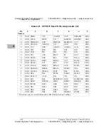
4-23
4
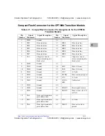
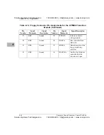
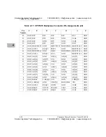
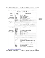
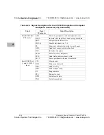
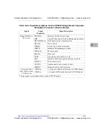
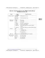
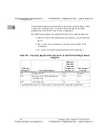
Table 4-22. Signal Descriptions for the CPV5370 Single Board Computer
Backplane Connector (J5)
Signal
Signal
Mnemonic
Signal Description
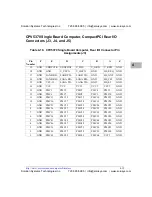
General
VCC
5V power supply
GND
Digital signal ground plane
Keyboard/Mouse
Device, TTL Levels
MCLK
Clock for PS/2 mouse
MDAT
Serial data line for PS/2 mouse
KBDCLK
Clock for PC/AT or PS/2 keyboard
KBDDAT
Serial data line for PC/AT or PS/2 keyboard
Miscellaneous
Signals
SPKR
PC/AT speaker output, open collector
DIAG
Diagnostic/alarm output, open collector
PBRESET
Pushbutton system reset input (pulled up, filtered,
and debounced on host card)
RESET
System reset output, TTL totem-pole
SM Bus Signals
SMBDATA
System Management Bus signals
SMBCLK
SMBALRT
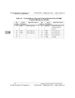
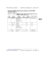
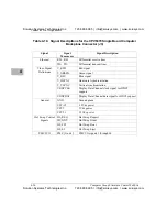
EIDE (ATA-2),
Secondary Channel,
TTL levels
IOCS16-
Indicates a 16 bit register is decoded
DMARQ
Drive DMA request
DMACK-
Drive DMA acknowledge
DIOR-
Drive I/O read
DIOW-
Drive I/O write
DASP-
Drive active/slave present
IORDY
Indicates drive is ready for I/O cycle(s)
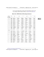
DD[15:0]
Drive data lines, bits 15--0
DRESET-
Reset signal to drive
CS1-
Chip select drive 0, also command register block
select
CS3-
Chip select drive 1, also command register block
select
DA[2:0]
Drive register and data port address lines
INTRQ
Drive interrupt request
PDIAG-
Output from drive 1 and monitored by drive 0
Solution Systems Technologies Inc.
720-565-5995 | [email protected] | www.solusys.com
Solution Systems Technologies Inc.
720-565-5995 | [email protected] | www.solusys.com


