1
101 Metro Plaza • Suite 315 • San Jose, CA 95110 •
(800) 801-4186
© 2020 SolPad Inc
.
SolPad Load Controller
Installation
Version 1.8 ● 06 February 2020
101 Metro Plaza, Suite 315, CA 95110
www.solpad.com
Страница 1: ...1 101 Metro Plaza Suite 315 San Jose CA 95110 800 801 4186 2020 SolPad Inc SolPad Load Controller Installation Version 1 8 06 February 2020 101 Metro Plaza Suite 315 CA 95110 www solpad com...
Страница 2: ...onnel Inadequately sized wiring and or overcurrent protection can cause serious injury or death to personnel and damage to equipment and or property WARNING Inadequate grounding methods conductors can...
Страница 3: ...ed 9 HVAC Connection A C and Heat Control via low voltage Fan is not controlled 9 Electric Kitchen Range controlled with 50 amp breaker 10 2 The SolPad Load Controller 11 2 1 Introduction 11 2 2 SolPa...
Страница 4: ...Power for the System 20 3 3 Connectivity and Accessories 20 4G Wi Fi RS485 21 3 4 Installation of Current Transducers CTs 22 Mains Grid Power 23 Battery Max Customers with AC Coupled Batteries 24 Batt...
Страница 5: ...aza Suite 315 San Jose CA 95110 800 801 4186 2020 SolPad Inc My clothes dryer turns on and tumbles but does not heat up is my dryer broken 30 What systems and appliances does the SolPad system typical...
Страница 6: ...ircuit Connection To control a typical 120v circuit in a residence you ll interrupt the line conductor at the breaker and land it on the relay in the load controller In the electric panel interrupt th...
Страница 7: ...er conductor from the relay s COM terminal back to the circuit breaker See 30 Amp DPDT Relay information in section 2 6 Pool or Spa HEATER 30A 240V As with Clothes Dryers you want to disconnect the le...
Страница 8: ...e relay s COM terminal back to the circuit breaker NOTE Advise the customer once wiring is complete that reprogramming of their Pool or Spa timer may be required and to take into account the On Peak p...
Страница 9: ...andler s transformer See 20 amp SPDT Relay information in section 2 6 HVAC Connection A C and Heat Control via low voltage Fan is not controlled For this configuration you ll interrupt the white W and...
Страница 10: ...oth L1 and L2 The 50 amp relay terminals are located on the yellow terminal block Interrupt L1 and L2 coming from the range and land them on their respective NC terminals on the 50 amp relay block The...
Страница 11: ...h slight variations IMPORTANT NOTE This Energy Management System is to be installed by a professional electrician 2 2 SolPad Load Controller Product Line SolPad carries four different Load Controller...
Страница 12: ...ther 4 20ma applications 6 CT Kit Provides installer with CT options should the supplied CTs not fit 7 Mounting hardware for the enclosure based on site requirements 8 14ga and 10ga stranded conductor...
Страница 13: ...connections to make sure they won t fall out during installation Also make sure the relays are all firmly seated in the black relay bases located on the middle right side of the panel The enclosure ma...
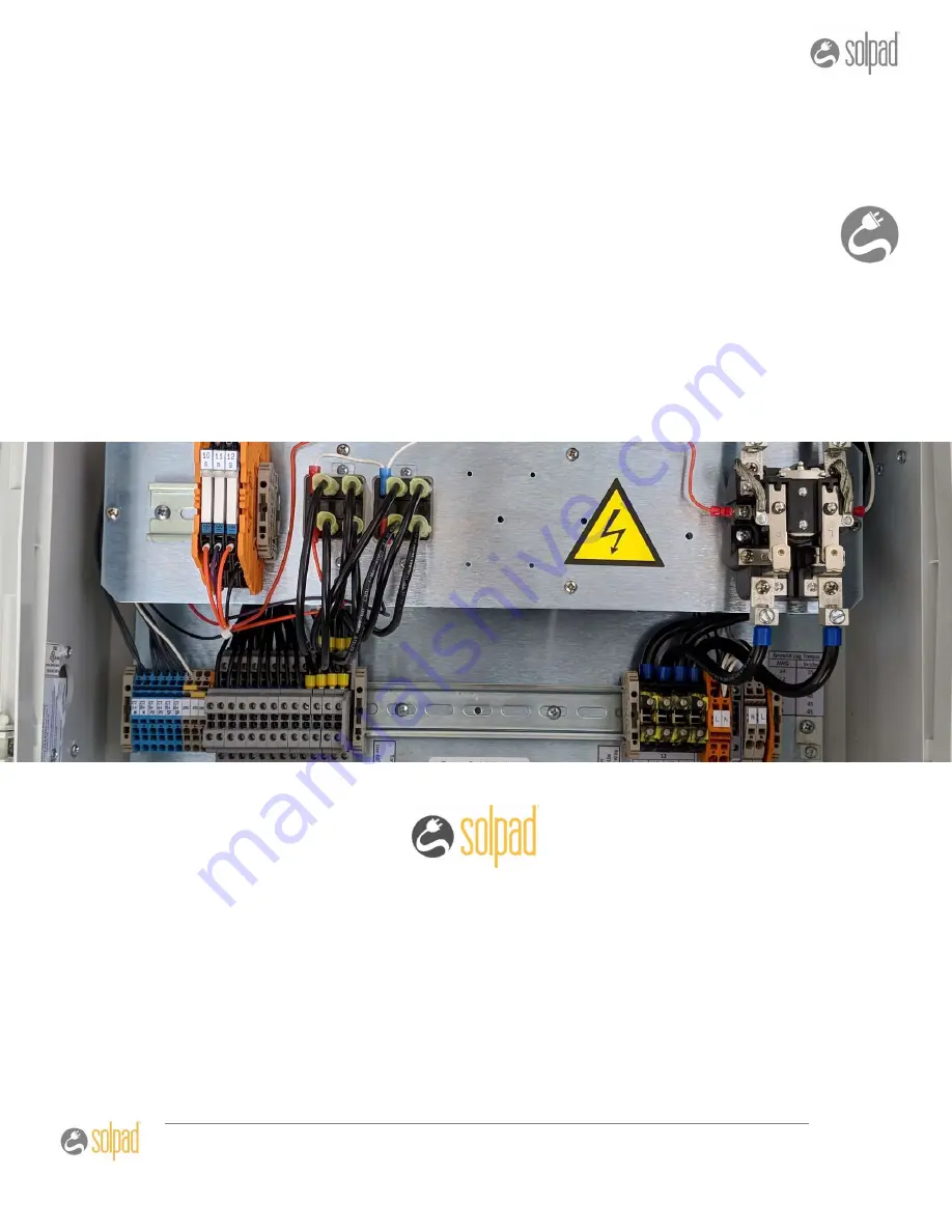
Страница 14: ...50 amp relay G 30 amp relays underneath mezzanine H Terminal block for CT s I Terminal block for 20 amp relays J Terminal block for 30 amp relays K Terminal block for 50 amp relays L 4 amp breaker AC...
Страница 15: ...ds to the relays The MOTEs are designated by a version number and physical position In the image below the mote on the left is version R1 1 R for Residential and 1 for the first position in the layout...
Страница 16: ...conjunction with relays to accommodate different load sizes O 1 3 on each The diagram below shows how the layout is wired to cover the ranges 4G High Gain Antenna RS485 Adapter Wi Fi Antenna The last...
Страница 17: ...ler contains between 4 26 of these relays depending on your model 30 Amp DPDT 240vac Relays The relay comes pre wired to a set of phoenix terminals mounted on a DIN Rail Each 30 amp relay has two posi...
Страница 18: ...E TO ADDRESS THE ITEMS BELOW COULD RESULT IN THE RELAY HEATING UP AND FAILING All lug connections to the relay terminals MUST be properly torqued AND VERIFIED AT INSTALLATION COMPLETION All lug set sc...
Страница 19: ...roller 7 System Verification Test and Turn up The Installation technician will be required to supply some of the items necessary to complete the installation as noted in the Recommended Material and R...
Страница 20: ...the load controller as follows A Land the ground wire on the ground lug A in picture B Land the Neutral white in the orange terminal labeled N B in picture C Land the Line black in the orange terminal...
Страница 21: ...e mounting hole with your unibit This antenna connects to the top left SMA port on the CPU and requires the gold adaptor as shown below Make sure the adapter and the antenna connector are tight to ens...
Страница 22: ...ome may be labeled with K and L terminals In this case the K is positive and the L is negative CT s are also labeled for the correct orientation when clipping them onto the wire The arrow label follow...
Страница 23: ...need to land on the MOTE 1 terminals This is the first pair of positions on the CT terminal block Only the top row positions are used The negative com ground leads can be landed in any of the six com...
Страница 24: ...set of CT s measures the utility One set measures the dedicated loads during an outage One set measures the solar production CT s measuring the utility will land in the terminals for MOTE 1 CT s measu...
Страница 25: ...measuring the utility will land in the terminals for MOTE 1 CT s measuring back up battery power flowing to the dedicated loads sub panel will land on the terminals for MOTE 2 Demand Customers with So...
Страница 26: ...se the examples in the special section to properly wire your controlled loads to the relays in the box The section contains illustrations for nine different load types Populate the Cover Label You sho...
Страница 27: ...LED indicator on the bottom left lit Do not use the CPU power button to power on off the CPU b The MOTEs will each have a red LED between the bottom two terminals that will flash three different ways...
Страница 28: ...wered has communication and is transmitting data between the MOTE and the CPU It make take a few minutes to get to this stage If not flashing quickly please see section 3 6 of the installation guide H...
Страница 29: ...oing to the load The relay for that load should click one way and then the other as they work through each one Measure the output voltage on the relay to verify that correct operation There should be...
Страница 30: ...t the day Utilities have power plants that are designed to run constantly and supply power continuously At peak times utilities often generate power using plants designed to run only during those peak...
Страница 31: ...le put a higher priority on savings so those systems may prevent the dryer from heating during the on peak time when power is most expensive Others although they want to save money will put a higher p...