SOLIS RHI-3.6K-48ES-5G Скачать руководство пользователя страница 41

10.5 Grid standard selection guide

For different countries and regions, corresponding grid code needs to be selected in the 

inverter LCD to meet the requirements of local network provider. 

This instruction indicates how to change the grid code and what code should be selected in 

different places.

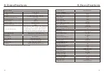
This following list illustrates the grid standard options in the inverter which are subject to 

change. It is for your reference only. If customer has any doubts or uncertainty, please 

consult Solis service department for confirmation.

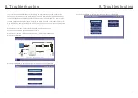
To set the correct grid code, please enter the following path:

Advanced Settings -> Password:0010 -> Select Standard

Detailed protection limits can be viewed when choosing the code. 

Please select "Save&Send" to enforce the code.

NOTE: 

Please check if the grid code setting comply with local requirement.

NO.

1

2

3

4

5

6

7

8

9

10

11

12

13

14

15

Code in LCD

VDE4015 

EN50549 PO

EN50549 NL

EN50438 L

France

C10/11

NRS097

CEI0-21

G98

G99

G98 NI

G99 NI

User-define

Country/Region

Germany

Poland

Netherland

France

Belgium

South Africa

Italy

UK

UK

North Ireland

North Ireland

Comments

For German Low Voltage Grid.

For Polish Low Voltage Grid

For Dutch Low Voltage Grid

General EN50438 Requirement. 

Possible to be used in Austria, Cyprus, Finland, 

Czech Republic, Slovenia, etc.

For French Low Voltage Grid

For Belgian Low Voltage Grid

For South African Low Voltage Grid

For Italian Low Voltage Grid

For UK Low Voltage Grid  <16A

For UK Low Voltage Grid  >16A

For North Ireland Low Voltage Grid  <16A

For North Ireland Low Voltage Grid  >16A

Customized Protection Limits

-

-

EIFS- SW

Sweden

For Swedish Low Voltage Grid

EN50549L

(EN50549-1)

General EN50549-1 requirement which meets 
local requirements of most European countries

16

Gen50 

Gen 60

DK1

Generator Connected, Frequency-Derating, 50Hz

Generator Connected, Frequency-Derating, 60Hz

For East Danish low voltage grid

-

-

-

17

18

East Denmark

NO.

Code in LCD

Country/Region

Comments

DK2

50438IE

RD1699

EN50549 L

For West Danish low voltage grid

For Irish low voltage grid

For Spanish low voltage grid

General EN50549 Requirement. 

Possible to be used in Cyprus, Finland, 

Czech Republic, Slovenia,Jamaica

19

20

21

22

West Denmark

Ireland

Spain

-

.78.

.79.

10. Appendix

10. Appendix

Содержание RHI-3.6K-48ES-5G

Страница 1: ...Industrial Park Xiangshan Ningbo Zhejiang 315712 P R China Tel 86 0 574 6578 1806 Fax 86 0 574 6578 1606 If you encounter any problem on the inverter please find out the inverter S N and contact us we...

Страница 2: ...5 Assembling the AC Connector 4 6 Meter Installation 4 7 Communication Cable Assembly 5 Operation 5 1 Initial Display 5 3 Information 5 4 Settings 4 2 3 Notice For Use 6 3 3 Terminal Connection 21 4...

Страница 3: ...1 Introduction 1 2 Packaging Please ensure that the following items are included in the packaging with your machine If anything is missing please contact your local Solis distributor RJ45 connector x...

Страница 4: ...AUTION Risk of electric shock from energy stored in capacitors of the Inverter do not remove cover for 5 minutes after disconnecting all power sources service technician only Warranty may be voided if...

Страница 5: ...2 The electrical installation must meet all the applicable regulations and standards 3 The inverter must be installed according to the instructions stated in this manual 4 The inverter must be install...

Страница 6: ...ept between inverters or objects and 500mm clearance between the bottom of the machine and the ground Visibility of the LEDs and LCD should be considered Adequate ventilation must be provided NOTE Not...

Страница 7: ...4 5 Wall Mount Bracket WARNING The inverter must be mounted vertically 2 Lift up the inverter be careful to avoid body strain and align the back bracket on the inverter with the convex section of the...

Страница 8: ...the terminal protection cover as indicated in Figure 4 7 Figure 4 7 Installation of Terminal Protection Cover Note Before connecting the battery please carefully read the user manual of the battery an...

Страница 9: ...re you use a cable within the correct speci cations as shown in the image below 3 Remove a length of 40mm of the cable jacket and strip the wire insulation to a length of 8 15mm 2 Lead the AC cable th...

Страница 10: ...bes the connection diagram of the Acrel 1ph meter With CT Standard Accessory for all other market exclude Italy Below 4 6 2 section describes the connection diagram of the Eastron 1ph meter Direct Ins...

Страница 11: ...formation please contact the sales manager For lead acid battery battery SOC calculation may not be accurate according to battery inconformity between cells battery aging or other specifications of le...

Страница 12: ...g to the standard line sequence of figure 4 13 connect the wire to the plug of RJ45 and then use a network cable crimping tool to make it tight Correspondence between the cables and the stitches of pl...

Страница 13: ...ating The inverter is initializing Fault condition is detected No fault condition detected Status ON OFF ON OFF OFF ON FLASHING Light POWER OPERATION ALARM 4 11 LED Indicates There are three LED indic...

Страница 14: ...Fail Critical Loads Loads connected to the AC Backup port which will be supported by battery and solar even if the grid is in malfunction Grid The arrow and value indicate the export import power of t...

Страница 15: ...26 27 Figure 5 8 Information Page 4 Settings Information 2015 02 23 19 35 4 4 Grid Meter Meter Voltage Meter Current Meter Power Meter Energy Input Energy 000 0V 00 00A 000000W 0000 00kWh ESC UP DOWN...

Страница 16: ...daily yield calculation If Solis monitoring system is used must set the correct time zone of the system otherwise datalogger will update the inverter time based on the time zone of the system Press UP...

Страница 17: ...16 Model Version and Software Version Battery Enable Disable 5 5 Advanced Information Detailed information can be viewed in this section 1 Alarm Message 2 Running Message 3 Version 4 Communication Dat...

Страница 18: ...ly Energy Figure 5 18 Daily Energy Daily Energy 2015 02 23 19 35 2015 23 02 00 10 20 30 40 50 60 D a i l y E n e r g y k W 00 00 03 00 06 00 09 00 12 00 15 00 18 00 21 00 00 00 ESC UP DOWN ENT The scr...

Страница 19: ...F Settings Warning Message 2015 02 23 19 35 Message Date Time Data NO message ESC UP DOWN ENT 5 5 9 Warning Message Figure 5 22 Warning Message Settings 5 5 8 Total Energy The screen shows the inverte...

Страница 20: ...Energy Adjusting total generating power 2015 02 23 19 35 Total Energy ESC UP DOWN ENT Y E S E N T N O E S C Total Energy 00000 kWh 56 This function is used to select corresponding grid standards Pleas...

Страница 21: ...wer 2015 02 23 19 35 Power Para ESC UP DOWN ENT Y E S E N T N O E S C Power Parameter 1 000 5 6 4 Reset Password Reset Password In this page user can reset the inverter password but the admin password...

Страница 22: ...y going into sleep mode when the ForceCharge SOC is reached inverter will charge the battery using the power from either PV or Grid NOTE If hybrid inverter is not connected to a battery select No Batt...

Страница 23: ...oating Current I_Max Discharge I_Max Charge Equalizing Voltage Force Charg Voltage 100Ah 53 5V 04 0V 010 0A ESC UP DOWN ENT 060 0V Overdischg Voltage 56 4A 44 5A 43 8V S ET E N T D ONE E S C Lead Acid...

Страница 24: ...Optional Eastron 3ph meter Direct Insert SDM630M Optional Eastron 3ph meter With CT SDM630MCT Optional No meter is connected 5 6 6 3 2 Meter Placement Grid Meter is installed at the grid connection p...

Страница 25: ...g polarity the inverter can protect itself from damage To avoid the possible damage during installation do not active battery wakeup function before nishing the rst commissioning 5 6 6 5 Battery Wakeu...

Страница 26: ...S C U P D AT E S Y S T E M E N T Figure 5 50 BaudRate RS485 Settings BaudRate RS485 2015 02 23 19 35 Y E S E N T N O E S C Baud Rate 9600 ESC UP DOWN ENT 5 6 10 BaudRate RS485 This function is to chan...

Страница 27: ...tivity otherwise it will lead to frequent false alarms or malfunctions Manufacturer is not responsible for any further damages caused by unauthorized modifications NOTE If you find your inverters s us...

Страница 28: ...witch between inverter and battery 4 Waiting for the LCD of inverter to turn off and the system shutdown is completed 1 Switch on the AC backup and AC grid 2 Select grid standard 3 Con gure the parame...

Страница 29: ...tion 2015 02 23 19 35 Warning Message Version Daily Energy Monthly Energy Yearly Energy Total Energy Running Message Communication Data Alarm Message KWH 2 526 0 00kW 0 00kW 0 00kW 0 00kW The inverter...

Страница 30: ...essage G IMP NO GRID OV BUS GRID INTF01 02 INI FAULT Failure description High grid impedance No grid voltage Over DC bus voltage Grid interference Initialization system fault Solution 1 Check connecti...

Страница 31: ...river connection UN G V01 02 12Power FAULT 12V power supply fault 1 Restart inverter or contact installer Table 8 1 Fault message and description 8 Troubleshooting Max input voltage Start up voltage M...

Страница 32: ...t AC Grid side Power Factor Max efficiency EU efficiency 0 99 0 8 leading 0 8 lagging 96 8 Max output current 15 7A 17 3A THDi 2 Efficiency Protection Ground fault monitoring Residual current mornitor...

Страница 33: ...V Max short circuit current 17 2A 17 2A Battery Output AC Back up Input AC Grid side Input voltage range Frequency range 184 264V 26 1A 45 55 Hz 55 65Hz Max input current 20ms Rated output power 5kW 4...

Страница 34: ...ncy range 184 264V 26 1A 45 55 Hz 55 65Hz Max input current 20ms Li ion Lead acid 100A 5kW Features Quick connection plug AC connection Communication Warranty RS485 Optional Wi Fi GPRS 5 years standar...

Страница 35: ...available in Belgium Features Quick connection plug AC connection Communication Warranty RS485 Optional Wi Fi GPRS 5 years standard extand to 20 years Display 7 0 LCD color screen display Grid connec...

Страница 36: ...inverter Make sure the polarities of battery is correct before connecting to the inverter Please follow the instructions below to choose the battery power cable NOTE Power cable uses water proofed AMP...

Страница 37: ...y item 1 rstly Then assemble back shell item 4 onto the connector body item 1 and tighten No gap When 16mm cable apply assembly barrelinto lug rstly as shown Then put the conductor into the lug Tie cl...

Страница 38: ...PV Battery Grid Battery Charging Power comes from PV If Charging From Grid is allowed it can also come from Grid If Time of Use is Run the logic will follow the charging discharging settings and time...

Страница 39: ...attery Load Support Priority PV Battery Grid Battery Charging Power comes from PV If Charging From Grid is allowed it can also come from Grid If Time of Use is Run the logic will follow the charging d...

Страница 40: ...nexpected control mistakes EPS Mode Path Advanced Settings Storage Energy Set Storage Mode Select EPS Mode EPS En Disable Enable Settings EPS Mode 2015 02 23 19 35 S ET E N T D OWN E S C Mode 4 Off Gr...

Страница 41: ...and Netherland France Belgium South Africa Italy UK UK North Ireland North Ireland Comments For German Low Voltage Grid For Polish Low Voltage Grid For Dutch Low Voltage Grid General EN50438 Requireme...

Отзывы: