


5. Operation
5. Operation
.43.
.42.
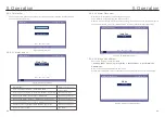
Settings
Lead Acid Battery
2015-02-23 19 35
Hot
Environment Temp
:
Y E S
=
< E N T >
N O
=
< E S C >
E S C
U P
D O W N
E N T
WARNING:
Lead-acid battery is not recommended for general customers as it requires
experienced installers and technicians who can fully understand the battery
parameters and configure the settings and installations correctly.
Due to the inconformity between battery cells, damages will be less likely to be
avoided. Solis is not responsible for any potential damages caused by the use
of lead-acid batteries.
NOTE:
5G products support lead-acid battery. Select "Lead-Acid" in the
"Battery Select" and configure the following parameters according
to different lead-acid batteries.
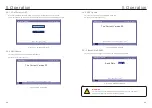
Settings
Lead Acid Battery
2015-02-23 19 35
Battery Capacity:
Floating
Voltage:
Floating Current:
I_Max Discharge:
I_Max Charge:
Equalizing Voltage:
Force Charg Voltage
:
100Ah
53.5V
04.0V
010.0A
E S C
U P
D O W N
E N T
060.0V
Overdischg Voltage
:
56
.
4A
44
.
5A
43
.
8V
S E T
=
< E N T >
D O N E
=
< E S C >
Lead Acid Battery (Values are examples Only)
Temp.Compensation:
072mV/degC
1. Battery Capacity: Define the capacity of the battery.
2. Equalizing Voltage: Define the voltage for equalizing charge.
3. Floating Voltage: Define the voltage for floating charge.
4. Floating Current: Define the current for floating charge.
5. Overdischg Voltage: Define the voltage that stops discharging the battery.
6. Force Charg Voltage: Define the voltage that forces to charge the battery
to prevent a dead battery.
7. I_Max Discharge: Define the max discharge current for the battery.
8. I_Max Charge: Define the max charge current for the battery.
9. Temp.Compensation: Define the temperature compensation parameter
for the battery.
After configuration, save and send. Select the Environment Temp based on
real condition.(Hot/Warm/Cold)


