71
70
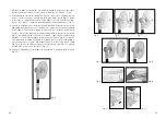
7. Fasten the rear protection grid using the rear nut (
4
). To do that, turn the rear
nut clock wisely towards “Tighten”. (
Fig. 5
)
8. Now, push the rotor blade onto the motor shaft as well. The 2 pins on the motor
shaft have to glide into the two grooves in the rotor blade base (
fig. 6
). Fasten
the rotor blade with the rotor blade nut (
2
) by turning it counter clock wisely
towards “Tighten”. The rotor blade should be able to turn freely afterwards.
(
Fig. 7
)
9. The frame ring connects the rear protection grid with the front protection grid.
First, remove the screw on the locking clip with a screwdriver and open the clip.
Place the frame ring on the rear protection grid (
fig. 8
), the guidance clip in
the frame ring (opposite the clip) has to lock onto a wire of the rear protection
grid (
fig. 9
). Then, each guidance jig on the frame ring has to lock onto the rear
protection grid. Therefore, you should push the frames toward each other with
your hand (
fig. 10
). At last, close the plastic clip (
fig. 11
) and fasten the screw
with a screwdriver. (
Fig. 12
)
10. Once the fan is properly assembled you can start using the appliance. (
Fig. 13
)
Fig. 5
Fig. 6
Fig. 7
Fig. 8
Fig. 9
Fig. 10
Fig. 11
Fig. 12
Fig. 13
Fig. 13


