


ORIGIN User Guide
Origin Master Section
24
MIX BUS Fader
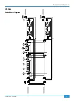
The main stereo MIX BUS fader is a 100mm high quality audio taper fader that controls the level of the main Mix Bus Out from the
console. The Mix Bus Fader is calibrated so that unity gain (0dB) is at the top of its travel. As can be seen in the block diagram
below, the fader follows the dedicated, balanced Mix Bus Insert Send and Return, which in turn is ahead of the classic SSL Bus
Compressor. An Oscillator inject is the last point in the Mix Bus signal flow, this inject is switched on using the
TO MIX
switch in
the Master Section
OSCILLATOR
controls.
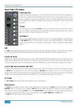
MIX BUS Insert
ORIGIN's Mix Bus has a dedicated, fully balanced Insert Send and
Return. The Insert Send is always active, with the Insert Return being
switched into the Mix Bus circuit using the
INSERT
switch located next to
the Mix Bus fader (see picture left). This Insert is an ideal place to insert
mix bus processing devices such as SSL's Fusion.
MIX BUS COMPRESSOR
The classic SSL Bus Compressor in ORIGIN is a stereo compressor
applied across the Main Mix bus that uses exactly the same classic
design as the original unit found on the SL4000 G-Series console released
in 1989 (which in-turn was evolved from the earlier E-Series consoles).
The ‘soft’ knee point of the compressor, ie. the level at which compression
starts to take place, is set by the
THRESHOLD
control (±20dB). This is
intentionally designed to change depending on the setting of the
RATIO
control; decreasing the
RATIO
setting lowers the effective threshold,
hence maintaining the perceived ‘loudness’ of the compressed signal.
The
RATIO
switch has six settings, 1.5:1, 2:1, 3:1, 4:1, 5:1 and 10:1.
ATTACK
time is switchable in six steps between 0.1 and
30 ms, and the
RELEASE
time is selectable between 0.1 and 1.6 seconds in five steps. The
AUTO
release selection adjusts the
release time according to the signal envelope. The gain
MAKEUP
simply acts as a level control to compensate for the lowered
level that is a consequence of compressing the signal. This control may be set so as not to change the overall output level when
the compressor is switched in.
The compressor features a classic ‘dominant’ sidechain architecture. The left and right channels are independently rectified using
a true peak full wave detector circuit, and the dominant (loudest) channel controls the gain reduction of the overall stereo level
via the user selected time constants.
Block Diagram of the main Mix Bus section
+
-
+
-
IN
+
-
+
-
BUS COMP
+
-
+
-
MIX L OUT
MIX R OUT
Main Mix Bus
MIX METER
FOLLOW MON
SOURCE
IN
S/C
VCA
INSERT
VCA
S/C
VCA
VCA
KEY
INSERT
INSERT
COMP
to 0dB
TONE
SLATE
From MON L
From MON R
SLATE
SIGNAL
STEREO
MIX
BUS
L R
STEREO
MIX
METERS
L R
Содержание ORIGIN
Страница 1: ...www solidstatelogic com ORIGIN User Guide ...
Страница 23: ...ORIGIN User Guide Detailed Channel Description 17 Channel Section Notes ...
Страница 55: ...49 ORIGIN User Guide Notes Notes ...
Страница 56: ...www solidstatelogic com ...