


The Centuri Processor
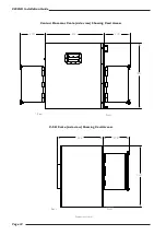
The Centuri processor is a 15U high 592mm deep rack unit. Cards are fitted to the front and rear of the chassis so space
for access is essential. See page 10 for chassis dimensions and minimum service clearance.
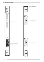
At the front of the processor are located the plug-in PSU units. One unit is capable of powering the system and a second
module may be ordered to provide power redundancy.
The panel below the power supplies is fitted with the Compact Flash memory card reader. This is used to transfer system
software onto the internal hard disk. Note that although a multiformat card reader is fitted, only the Compact Flash card
format is currently supported. The system’s hard-drive is located behind this panel. A second, redundant hard-drive can be
specified as an option. If this feature is ordered, a second identical drive, which also contains the system software, is fitted
and a front panel key switch is provided for disk selection.
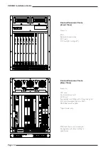
Below the drives is the front card-cage which has space for 11 plug-in cards, numbered from left to right. The cards are
arranged as follows:
Slots 1–4
Channel DSP cards.
Slot 5
Always fitted with a master DSP card for mix processing.
Slot 6
Optional 2nd master DSP card for enhanced 2Fs bus capacity and processing.
Slots 7–10
Can be a combination of additional DSP cards and/or micamp cards (digital or MADI cards to
special order only)
†
.
Slot 11
Always blank.
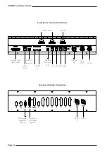
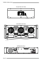
There rear of the processor has space for 12 plug-in cards. Note that these slots are numbered from right to left.
Slots 1–4
Available for I/O cards (analogue, digital and MADI).
Slot 5
Always fitted with the console’s Routing/Link card.
Slot 6
Reserved for the optional GPI/O card.
Slots 7–10
I/O cards – analogue, digital and MADI (mic cards to special order only)
†
.
Slot 11
Always fitted with the Console-Interface card.
Slot 12
Always fitted with the CPU card.
Note that front and rear mounting I/O cards, although functionally identical, are physically different so it is not possible to
exchange cards between back and front.
At the rear of the rack is the connector for the DAW interface panel. When the DAW control option is specified a separate
1U Midi breakout panel and connecting lead is provided. See page 45 for additional information.
† Specifying rear mounted micamp cards or front mounted digital/MADI cards will extend the order lead time.
System Components
Section 4
Page 15
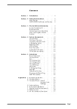
Содержание C300 HD
Страница 1: ...Installation Guide ...
Страница 2: ...C300HD Installation Guide ...
Страница 70: ...C300HD Installation Guide Page 66 4dBu 1 229V rms 0dBu 0 775V rms 6dBu 0 388V rms ...
Страница 74: ...C300HD Installation Guide Page 70 volume of a sphere 4 π r 3 3 ...
Страница 76: ...C300HD Installation Guide Page 72 Notes ...