background image

With both charge faucets now open, run the Flojet pressure pump until the pinkish glycol mixture begins flowing into the empty 

bucket. Quickly switch the hose from the empty/return bucket to the bucket containing the glycol mixture. Continue to circulate 

the fluid using the pressure pump until the bubbling has stopped and the air has been purged.

After charging the collector loop, shut the lower charge faucet and let the pressure pump drive up the loop pressure to the 

appropriate level (Generally in the range of 25 psi). To more accurately calculate the proper pressure measure the height of the 

solar collector above the solar storage tank and divide this number by 2.31. Then add 20 psi to this number. As a word of caution, 

the pressure in the glycol loop should not exceed 45 psi when the system is operational on a good sunny day.

After you have determined the integrity of the entire piping system turn on the circulating pump. Do this by setting the manual 

switch within the controller to the “on” position. Run the pump for a full five minutes and carefully check to ensure there is 

proper fluid flow and that all the air has been purged from the solar collector glycol loop. An inexpensive flow meter such as 

manufactured by Blue White Industries or Letro is recommended as an optional system component. A flow meter allows you to

monitor and adjust the flow rate through the piping and also to visually inspect the HTF fluid quality.

Set the controller to the “off” position and proceed to the next step.

Mix the propylene glycol and distilled water mixture in accordance with Table 4 and Table 5 in a large clean bucket. You will need 

a second empty bucket as well. The charging process also will require a low flow diaphragm pump (Flojet or equal) to fill and 

pressurize the collector loop.

Connect the discharge side of the pressure pump to the upper charge faucet. Place the pump suction side hose in the glycol 

solution. Close the isolation ball valve and connect a second hose to the lower charge faucet. Place the other end of the hose in 

the empty bucket. Open the upper charge faucet and allow the pressure from the expansion tank to push the water in the glycol 

loop back to prime the pressure pump. When the hose in the bucket containing the glycol mixture stops bubbling you may begin 

charging the collector loop with glycol.

8.

9.

4.

5.
6.

7.

CHARGING THE SYSTEM. 

-


13

10. Charging the System. 

- Cont.

INSTALLATION MANUAL SOLENE

®

 HOT WATER SYSTEMS

©

2014 UMA Solar

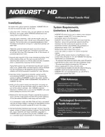
SYSTEM PROTECTION - 

Freeze is the temperature where the first ice crystal forms in the fluid. Flow is the temperature where the

fluid will contain ice crystals but still flow. Burst is the temperature where the fluid is solid, expanding and bursting the vessel.

*THE AO SMITH SUNX 80 OR SUNX 120 HEAT EXCHANGER HAS A 2.8 OR 4 GALLON FLUID CAPACITY. THIS TABLE ASSUMES A TOTAL 

100 foot PIPE RUN USING ¾” TYPE M HARD COPPER TUBING.

CONTACT YOUR SOLAR CONTRACTOR IF THE CHARGED COLLECTOR LOOP PRESSURE EXCEEDS THIS THRESHOLD.

100%

-60°F

-70°F

-100°F

75%

-60°F

-60°F

-100°F

50%

-30°F

-40°F

-75°F

40%

-7°F

-15°F

-60°F

35%

0°F

-10°F

-60°F

Noburst HD

Freeze Point

Flow Point

Burst Point

Содержание SLAR32DC-75HE-G

Страница 1: ...C 80HE SLAR64DC 120HE XE SLAR64DC 80HE XE SLAR64DC 120HE XG SLAR64DC 80HE XG SLAR64DC 120HE SLAR64DC 80HE SLAR80DC 120HE XE SLAR80DC 80HE XE SLAR80DC 120HE XG SLAR80DC 80HE XG SLAR80DC 120HE SLAR80DC 80HE SLSG80DC 120HE XE SLSG80DC 80HE XE SLSG80DC 120HE XG SLSG80DC 80HE XG SLSG80DC 120HE SLSG80DC 80HE SLCO32DC 80HE XE SLCO32DC 80HE XG SLCO32DC 80HE SLCO40DC 80HE XE SLCO40DC 80HE XG SLCO40DC 80HE ...

Страница 2: ...120HE XG SLAR64DC 80HE XG SLAR64DC 120HE SLAR64DC 80HE SLAR80DC 120HE XE SLAR80DC 80HE XE SLAR80DC 120HE XG SLAR80DC 80HE XG SLAR80DC 120HE SLAR80DC 80HE SLSG80DC 120HE XE SLSG80DC 80HE XE SLSG80DC 120HE XG SLSG80DC 80HE XG SLSG80DC 120HE SLSG80DC 80HE SLCO32DC 80HE XE SLCO32DC 80HE XG SLCO32DC 80HE SLCO40DC 80HE XE SLCO40DC 80HE XG SLCO40DC 80HE SLCO60DC 80HE SLCO64DC 120HE XE SLCO64DC 80HE XE SL...

Страница 3: ...bing items and materials Be sure to use quality products that will withstand direct sunlight year after year Please take care to avoid hazards such as overhead electrical wires or loose shingles Be sure to secure ladders so they will not slip or fall Do not allow extension cords to lie in standing water Wear shoes with proper tread to prevent slipping on the ladder or sloped roof areas Disconnect ...

Страница 4: ...fferential Control SLSG40DC 80HE XE 30004071 1 71 80 1 SLSG 40 Differential Control SLSG40DC 80HE XG 30004074 0 98 80 1 SLSG 40 Differential Control SLSG40DC 80HE 30004068 1 99 120 2 SLAR 32 Differential Control SLAR64DC 120HE XE 2010142D 2 5 80 2 SLAR 32 Differential Control SLAR64DC 80HE XE 2010142B 2 66 120 2 SLAR 32 Differential Control SLAR64DC 120HE XG 2010143D 1 28 80 2 SLAR 32 Differential...

Страница 5: ...nk shall have an additional insulation jacket 80 1 SLAR 32 Differential Control SLCO32DC 80HE 2006023A 1 25 80 1 SLAR 40 Differential Control SLCO40DC 80HE XE 2006029B 1 21 80 1 SLAR 40 Differential Control SLCO40DC 80HE XG 2006025B 0 75 80 1 SLAR 40 Differential Control SLCO40DC 80HE 2006023B 1 31 80 2 SLCO 30 Differential Control SLCO60DC 80HE 2006023C 1 45 120 2 SLAR 32 Differential Control SLC...

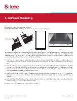
Страница 6: ...rdware There are two sets each for the top and bottom Once the collector s location is determined anchor two 2 flush mount brackets to the roof using two 2 stainless steel 3 8 lag bolts for each bracket Each bolt should be sealed using an appropriate roof sealant in order to prevent any possible leaks from penetrating the roof members The flush mount brackets should be spaced so the lag bolts pene...

Страница 7: ...od After the collector s are installed it should resemble a skylight The flush mount gripper 1 5060 030 consists of four 4 U channels four 4 grippers four 4 strut nuts with springs and associated hardware There are two sets each for the top and bottom Once the collector s location is determined anchor two 2 U channel to the roof using two 2 stainless steel 3 8 lag bolts for each U channel Each bol...

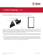
Страница 8: ...he latch into the top of the U channel so that the gripper remains on top of the opening Place them at the middle of the U channel s top and tighten Fig 4 Loosen the gripper providing space to insert the slot at the collector s edge between the Gripper s hook and the U channel s top Once both grippers are grabbing the collector s edge slot tighten both grippers Fig 5 6 Repeat steps 2 5 for the top...

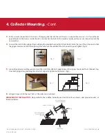
Страница 9: ...ountingmethod Assemble the mounting clips to both U channels utilizing the provided bolts Fig 7 Screw the mounting clips to the BOTTOM part of the collector the weep hole side using two 2 stainless steel self drilling screws each Fig 10 Mounting clips may also bolt into collector frame slot using 1 5 16 carriage bolt nut and washer 1 2 3 4 Fig 8 Fig 10 Fig 11 Fig 12 Fig 9 Assemblebothtiltlegsandto...

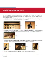
Страница 10: ...llector s top with the assembled tilt leg kits and anchor the U channels to the roof ensuring the proper angle to the collectors Fig 14 Use compatible sealant and roof flashing as required INSTALL ALL COMPONENTS IN ACCORDANCE WITH LOCAL CODE SO THAT THE PERFORMANCE OF ANY STRUCTURAL MEMBER OR FIRE RATED ASSEMBLY IS NOT REDUCED ...

Страница 11: ...tion pump shall be pre wired with a 6 line cord so that it can be plugged directly into the 115 volt receptacle on the differential control Repairs or routine system maintenance can be completed without introducing air into the system or draining the HTF AhighqualitythermostaticmixingvalveisarequiredcomponentinallOG 300certifiedsystemsandshouldbeplumbedinlinewith brass union connections for ease o...

Страница 12: ...he storage tank or to the wall if closer than 5 feet The storage tank should not be placed directly on an un insulated floor or concrete slab The tank should be placed on a well insulated pad with a minimum R value of 10 An R 20 insulated tank is recommended for all Solene systems If your tank needs additional insulation an Insulation Jacket is recommended Frost King or equal Fig 17 Fig 16 Fig 15 ...

Страница 13: ...uld be properly supported approximately every 6 The support clamps should be installed in a way as to not compress the pipe insulation The Differential Control has a high limit storage setting that can be adjusted from 110 F to 200 F and is typically preset to 140 F It is very important to verify that the high limit is set and engaged per manufacturer s instructions This will prevent overheating i...

Страница 14: ...onal If your solar contractor is not allowed by law to make these connections consult a licensed electrician NEVER ACTIVATE THE CIRCUIT BREAKER CONTROLLING THE ELECTRICAL HEATING ELEMENT UNTIL THE SOLAR STORAGE TANK IS COMPLETELY FILLED WITH WATER This will prevent dry firing of the heating element The electrical heating element will be destroyed almost instantaneously if not completely submerged ...

Страница 15: ... off position and proceed to the next step Mix the propylene glycol and distilled water mixture in accordance with Table 4 and Table 5 in a large clean bucket You will need a second empty bucket as well The charging process also will require a low flow diaphragm pump Flojet or equal to fill and pressurize the collector loop Connect the discharge side of the pressure pump to the upper charge faucet...

Страница 16: ...ged and the pressure is around 25 psi check the pressure gauge set the differential controller to the Automatic setting This will activate your circulating pump NOBURST CHARACTERISTICS INHALATION Move person to fresh air if effects occur consult a physician EYECONTACT Flusheyesthoroughlywithwaterforafewminutes Removecontactlensesaftertheinitial1 2minutesandcontinue flushing for several additional ...

Страница 17: ...ff at specified times throughout the day if desired TheGoldlinecontrollerallowsyoutosetthe on differential Turntheredrotaryswitchinsidethecontrolhousingto12 Thecontroller also allows you to limit the finished solar storage tank temperature if desired Turn the red rotary switch inside the controller marked Hi Limit to the 160 setting Solene does not recommend that the Hi Limit be set any lower than...

Страница 18: ... 530C Adjustable Pressure Relief Valve or equal used to relieve excess pressure from heat transfer fluid loop If fluid is expelled call your dealer immediately Ranges of adjustment are 50 to120 psi Line Thermometers 1 5020 028 Line Thermometer w temperature range of 50 F to 220 F Hot Water Thermometer 1 5020 028 Line Thermometer w temperature range of 50 F to 220 F Mixing Valve Watts 1 5115 015 Mi...

Страница 19: ...ecified by the Insulation Manufacturer Roof Penetration Flashing All Copper Roof Flashing Gooseneck type flashing is recommended for feed line to accommodate sensor wire Existing Hot Water Tank for two tank systems Serves as a storage tank for hot water produced by solar system 13 Component Parts List Functions Cont INSTALLATION MANUAL SOLENE HOT WATER SYSTEMS 2014 UMA Solar To comply with SRCC ce...

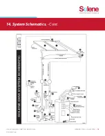
Страница 20: ...COMPONENTS PARTS LIST FUNCTIONS 18 INSTALLATION MANUAL SOLENE HOT WATER SYSTEMS 2014 UMA Solar 14 System Schematics SLAR40DC 80HE SLSG40DC 80HE ...

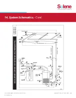
Страница 21: ...COMPONENTS PARTS LIST FUNCTIONS 19 INSTALLATION MANUAL SOLENE HOT WATER SYSTEMS 2014 UMA Solar 14 System Schematics Cont SLSG80DC 80HE SLAR80DC 80HE XE SLAR64DC 80HE XE SLAR48DC 80HE XE ...

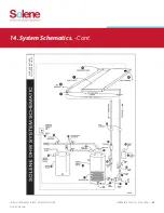
Страница 22: ...INSTALLATION MANUAL SOLENE HOT WATER SYSTEMS 2014 UMA Solar 14 System Schematics Cont COMPONENTS PARTS LIST FUNCTIONS 20 SLAR40DC 80HE XE SLSG40DC 80HE XE ...

Страница 23: ...COMPONENTS PARTS LIST FUNCTIONS 21 INSTALLATION MANUAL SOLENE HOT WATER SYSTEMS 2014 UMA Solar 14 System Schematics Cont SLAR80DC 80HE XE SLAR64DC 80HE XE SLAR48DC 80HE XE SLSG80DC 80HE XE ...

Страница 24: ... 22 COMPONENTS PARTS LIST FUNCTIONS INSTALLATION MANUAL SOLENE HOT WATER SYSTEMS 2014 UMA Solar 14 System Schematics Cont SLAR4DC 80HE XE SLSG40DC 80HE XG ...

Страница 25: ...COMPONENTS PARTS LIST FUNCTIONS 23 INSTALLATION MANUAL SOLENE HOT WATER SYSTEMS 2014 UMA Solar 14 System Schematics Cont SLSG80DC 80HE XG SLAR80DC 80HE XG SLAR64DC 80HE XG SLAR48DC 80HE XG ...

Страница 26: ......

Страница 27: ......

Страница 28: ... embossed foil Fluid may be discharged at hight temperature and or pressure Underground piping Stay clear during any thunderstorm activity Underground piping Stay clear during any thunderstorm activity Fluid may be discharged at hight temperature and or pressure WARNING WARNING WARNING WARNING HOT WARNING HOT WARNING HOT WARNING No other fluid shall be used that would change the original classific...

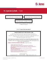
Страница 29: ...water in the solar loop to drain into a sink or a location outside CAUTION WATER MAY BE EXTREMELY HOT Maximum Operating F P F F Place these labels on Solar Bypass Valves as detailed in schematics on page 10 SOLENE FREEZE PROTECTION INSTRUCTIONS 15 System Labels Cont Solar Enabled Open Solar Bypass Closed Solar Enabled Open Solar Bypass Closed Solar Enabled Open Solar Bypass Closed Your Solene Sola...

Страница 30: ...ng System MODELS SLAR40DC 80HE XE SLAR40DC 80HE XG SLAR40DC 80HE SLSG40DC 80HE XE SLSG40DC 80HE XG SLSG40DC 80HE SLAR64DC 120HE XE SLAR64DC 80HE XE SLAR64DC 120HE XG SLAR64DC 80HE XG SLAR64DC 120HE SLAR64DC 80HE SLAR80DC 120HE XE SLAR80DC 80HE XE SLAR80DC 120HE XG SLAR80DC 80HE XG SLAR80DC 120HE SLAR80DC 80HE SLSG80DC 120HE XE SLSG80DC 80HE XE SLSG80DC 120HE XG SLSG80DC 80HE XG SLSG80DC 120HE SLSG...

Отзывы: