background image


SOLE S.A.  –  Solar Collectors  –  Installation Manual 


19

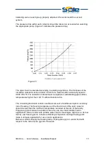
Freezing Point 

Propylene Glycol Solution 

(% by mass) 

10 

20 

30 

40 

50 

60 

Temperature 

(

o

C) 

-3 

-8 

-14 

-22 

-34 

-48 


The primary circuit of the solar collectors must be in accordance with all the 
necessary security measures, particularly a safety valve correctly set, an expansion 
tank designed to even take into account the evaporation of liquid contained in the 
collectors and a system of protection against overheating (heat sink or similar), if 
necessary.  
 
The primary circuit of the solar collectors must have at least a thermometer and a 
manometer to permit recording of the temperature and the pressure of the circuit.  
 
Before the final filling of the primary circuit, internal washing with domestic water 
should be carried out to remove any dirt or rests and pressure test should be carried 
out to verify the sealing of all, without exceeding the maximum pressure allowed by 
solar collectors. This is to verify that the connections between solar collectors have 
no leaks. If that is so, the fittings should be tightened, using two keys, so as to avoid 
transmitting force (tortion) to the pipes of the absorbers of the solar collectors.  
 
During the final filling of the solar system with antifreeze fluid it must be verified that 
the circuit is perfectly purged and pressurized. Once this operation is finalized, the air 
vents should be closed.  
 
It should be avoided to carrying out operations such as washing and filling the 
primary circuit while or after the solar collectors are exposed to intense sun.  
 
 
8. Lightning Protection 
National norms and regulations over lightning protection should be closely followed. 
In any case the support(s) of the collectors must be “earthed” with copper wire of 
16mm

2

 to the ground grid of the building. This will serve as lightning protection. 

 This guideline does not release in any way the installer from his responsibility 
against lightning protection requirements. 
 
 
9. Permissible wind and snow load 
Permissible negative pressure for wind load is 1500 Pa     
Permissible positive pressure for snow load is 2000 Pa    


Содержание 1,75

Страница 1: ...SOLE S A Solar Collectors Installation Manual GB SOLAR COLLECTORS INSTALLATION MANUAL MODELS 1 75 2 00 2 50 2 70...

Страница 2: ...allation 11 5 1 Installation of longitudinal profiles D3 and Z angle E1 E2 11 5 2 Installation of vertical legs A3 and the long cross pieces X1 1 X2 13 5 3 Installation of vertical legs A3 and the lon...

Страница 3: ...before starting the installation that he has all the necessary parts and all the security measures have been taken in order to carry out the installation safely The installer must use protective glove...

Страница 4: ...Side 20 mm glass wool back 40 mm rock wool Casing Aluminium profile epoxy powder oven painted Free of bolts and rivets Sea Water resistant Glass Tempered low iron prismatic glass 4 mm Sealing EPDM Ru...

Страница 5: ...antaneous energy efficiency curve of solar collector Figure 2 Efficiency curve of Selective Collector 2 2 Support Frame There are two sets of support frames for a single collector EST1 or for two coll...

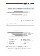
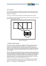
Страница 6: ...4 Figure 3 Support frame components EST1 for a single solar collector Figure 4 Support frame components EST2 for two solar collectors The support frames allow the installation of the solar collectors...

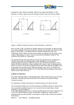
Страница 7: ...uld be carried out respecting the instructions of the person in charge of the project who should have taken into consideration the effect of the orientation inclination and possible shadows in the cal...

Страница 8: ...thickness and size of the bench should be sufficient to ensure stability of the whole in case of strong gusts of wind In any case the solution adopted should ensure the solidity and stability of the s...

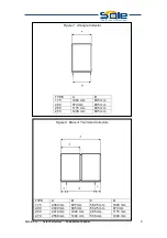
Страница 9: ...A B 1 75 1000 mm 895 mm 2 00 970 mm 895 mm 2 50 1175 mm 895 mm 2 70 1248 mm 895 mm Figure 8 Bank of Two Solar Collectors TYPE A B C D 1 75 2060 mm 895 mm 582 5 mm 1000 mm 2 00 2000 mm 895 mm 552 5 mm...

Страница 10: ...895 mm 552 5 mm 970 mm 650 mm 895 mm 2 50 3645 mm 1440 mm 485 mm 1175 mm 685 mm 895 mm 2 70 3864 mm 1440 mm 558 mm 1248 mm 794 5 mm 895 mm Figure 10 Bank of Four Solar Collectors TYPE A B C D E 1 75 4...

Страница 11: ...439 mm 582 5 mm 970 mm 650 mm 895 mm 2 50 6115 mm 1440 mm 485 mm 1175 mm 685 mm 895 mm 2 70 6480 mm 1440 mm 558 mm 1248 mm 794 5 mm 895 mm Figure 12 Bank of Six Solar Collectors TYPE A B C D E 1 75 63...

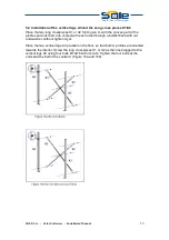
Страница 12: ...allation of the longitudinal profiles D3 and the Z angles E1 E2 Place the two longitudinal profiles D3 on the floor at the indicated distance so that both profiles U remain outward oriented Place the...

Страница 13: ...SOLE S A Solar Collectors Installation Manual 12...

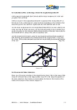
Страница 14: ...link them into contact with each other through a bolt M10x20 with nut and washer without tighten it yet Place the two vertical legs A3 parallel on the floor so that both U profiles are oriented toward...

Страница 15: ...oles depending on the inclination that wants to be given to the collectors Both profiles should be horizontal Screw with the two bolts M10x16 in each profile with its respective nuts Join the structur...

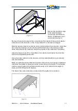
Страница 16: ...re match those holes back of the collectors Adjust the position of the collectors if necessary Adjust the higher cross E1 or E2 profile to the collectors and tighten the bolts that bind to the longitu...

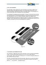
Страница 17: ...roof With the installation fittings are supplied some perforated flexible metal strips to facilitate this fixation on certain roof configurations See fig 19 The collectors and the support system can...

Страница 18: ...s of solar collectors with each other and or pipes of hydraulic circuit must be made so as to ensure that expansion does not cause excessive pressure tensions on the connections or on the collectors f...

Страница 19: ...atures higher than 120 C without deteriorat ion The circulating fluid must contain a sufficient amount of antifreeze liquid to avoid any risk of freezing The freezing temperature of the fluid circuit...

Страница 20: ...is to verify that the connections between solar collectors have no leaks If that is so the fittings should be tightened using two keys so as to avoid transmitting force tortion to the pipes of the ab...

Страница 21: ...tightness in the closed circuit connections and the entry and exit of each collector and the connections between them Fix if necessary or replace items parts in poor condition The support of solar col...

Страница 22: ...shed July 2008 Version 3 SOLE S A SOLAR DOMESTIC APPLIANCES MANUFACTURER Lefktron Laikon Agonon 136 71 Acharnai Athens Greece Tel 30210 2389500 Fax 30210 2389502 Email export sole gr www eurostar sola...

Отзывы: