background image

MANUFACTURER’S 

LIMITED WARRANTY 

Dyaco Canada Inc. warrants all its 

air bike

 parts for a period of time listed below from the date of retail sale, as

determined by sale receipt, or in the absence of a sales receipt eighteen (18) months from the original factory shipping 
date. Dyaco 

Canada Inc.’s responsibilities include providing new or remanufactured parts, at Dyaco Canada Inc.’s 

option, and technical support to our independent dealers and servicing organizations. In the absence of a dealer or 
service organization, these warranties will be administered by Dyaco Canada Inc. directly to a consumer. The warranty 
period applies to the following components: 

Frame 

 lifetime 

Parts  
Labour  

 1 year 

This warranty applies only to products in ordinary household use, and the consumer is responsible for the items listed 
below: 

1.

The warranty registration card must be completed and returned to the address listed on the card within 10 days of the


original purchase to 

validate the Dyaco Canada Inc.’s limited warranty.

2.

Proper use of the 

air bike

 in accordance with the instructions provided in this manual.

3.

Proper installation in accordance with instructions provided with the 

air bike

.

4.

Expenses for making the 

air bike

 accessible for servicing, including any item that was not part of the 

air bike

 at the


time it


was shipped from the factory.

5.

Damages to the 

air bike

 finish during shipping, installation or following installation.

6.

Routine maintenance of this unit as specified in this manual. 

EXCLUSIONS 

This warranty does not cover the following: 

1.

CONSEQUENTIAL, COLLATERAL, OR INCIDENTAL DAMAGES SUCH AS PROPERTY DAMAGE AND
INCIDENTAL EXPENSES RESULTING FROM ANY BREACH OF THIS WRITTEN OR ANY IMPLIED WARRANTY.

2.

Service call reimbursement to the consumer. Service call reimbursement to the dealer that does not involve


malfunction or defects in workmanship or material, for units that are beyond the warranty period, for units that are


beyond the service call reimbursement period, for 

air bike

 not requiring component replacement, or 

air bike

 not in


ordinary household use.

3.

Damages caused by services performed by persons other than authorized Dyaco Canada Inc. service companies;


use of parts other than original Dyaco Canada Inc. parts; or external causes such as corrosion, discoloration of paint


or plastic, alterations, modifications, abuse, misuse, accident, improper maintenance, inadequate power supply

 if 

applicable

, or


acts of God.

4.

Products with original serial numbers that have been removed or altered.

5.

Products that have been: sold, transferred, bartered, or given to a third party.

6.

Products that do not have a warranty registration card on file at Dyaco Canada Inc. Dyaco Canada Inc. reserves the


right to request proof of purchase if no warranty record exists for the product.

7.

THIS WARRANTY IS EXPRESSLY IN LIEU OF ALL OTHER WARRANTIES EXPRESSED OR IMPLIED,


INCLUDING THE WARRANTIES OF MERCHANTABILITY AND/OR FITNESS FOR A PARTICULAR PURPOSE.

8.

Product use in any environment other than a residential setting.

9.

Warranties outside of North America may vary. Please contact your local dealer for details. 

SERVICE 

B

y the serial number establishes the labour warranty period should service be required. If service is performed, it is in


your best interest to obtain and keep all receipts. This written warranty gives you specific legal rights. Service under this 
warranty must be obtained by following these steps, in order: 

1.

Contact your selling authorized SOLE dealer OR

 Dyaco Canada Inc.

2.

If you have any questions about your new product or questions about the warranty contact Dyaco Canada Inc. at 1-

888-

707-1880.

3.

If no local service is available, Dyaco Canada Inc. will repair or replace the parts, at Dyaco Canada Inc.’s option, within


the warranty period at no charge for parts. All transportation costs, both to our factory and upon return to the owner,


are the responsibility of the owner. The owner is responsible for  adequate packaging upon return to Dyaco Canada


Inc. Dyaco Canada Inc. is not responsible for damages that occur during shipping. Make all freight damage claims with


the  appropriate  freight  carrier.  DO  NOT  SHIP ANY  UNIT  TO  OUR  FACTORY  WITHOUT  A RETURN


AUTHORIZATION NUMBER. All units arriving without a return authorization number will be refused.

4.

For any further information, or to contact our service department by mail, send your correspondence to: 

Dyaco Canada Inc. 

5955

 Don Murie Street

Niagara Falls, ON 
L2G 0

A9

Product features or specifications as described or illustrated are subject to change without notice. 
All warranties are made by Dyaco Canada Inc.

 1 year 

-

30

 -

Содержание 16208768000

Страница 1: ......

Страница 2: ...structions Operation of Your New Air Bike Using Heart Rate Monitor Trouble Shooting Exploded View Diagram Parts List Training Guidelines Manufacturer s Limited Warranty ATTENTION THIS AIR BIKE IS INTENDED FOR RESIDENTIAL USE ONLY AND IS WARRANTED FOR THE APPLICATION ANY OTHER APPLICATION VOIDS THIS WARRANTY IN ITS ENTIRETY 23 25 30 1 ...

Страница 3: ... warranty contact Dyaco Canada Inc at 1 888 707 1880 Please take a moment at this time to record below the name of the dealer their telephone number and the date of purchase for easy contact in the future We appreciate your confidence in SOLE and we will always remember that you are the reason that we are in business Please complete and mail your registration card today and enjoy your new Air Bike...

Страница 4: ...d possibly scratch or damage the surface of your floor 6 No changes must be made which might compromise the safety of the equipment 7 It is recommended to have a minimum of 2 safe clearance around the exercise equipment while in use 8 Do not allow children to use or play on the air bike Keep children and pets away from this equipment at all times while exercising 9 The air bike should only be used...

Страница 5: ... to order a replacement decal Apply the decal in the location shown WARNING BEFORE BEGINNING ANY EXERCISE PROGRAM CONSULT YOUR PHYSICIAN THIS IS ESPECIALLY IMPORTANT FOR INDIVIDUALS OVER THE AGE OF 35 OR PERSONS WITH PRE EXISTING HEALTH PROBLEMS READ ALL INSTRUCTIONS BEFORE USING ANY FITNESS EQUIPMENT WE ASSUME NO RESPONSIBILITY FOR PEROSNAL INJURY OR PROPERTY DAMAGE SUSTAINED BY OR THROUGH THE US...

Страница 6: ... body in shape and achieving a happier and healthier lifestyle Before reading further please review the drawing below and familiarize yourself with the parts that are labeled Read this manual carefully before using the Sole SB800 Air Bike Although Dyaco Canada Inc constructs its products with the finest materials and uses the highest standards of manufacturing and quality control there can sometim...

Страница 7: ...e bar L R Console tube Console J1 Screw M8 60 J2 Screw M8 30 J3 Spacer Ring J5 Screw M6 16 J6 Screw M10 20 J4 NUT M8 Tool Wrench Screw driver Metal fixing plate H2 Pedal right H1 Pedal left G 1 Foot Support G 2 End Cap Customized Wrench 15 6m m 5m m 4m m 13 17 ...

Страница 8: ... STEP2 thefrontstabilizer B onto mainframe A andtight J6 Step 1 Loosen the two screws J6 from the paper strap STEP 2 the rear stabilizer C onto main frame A and J6 HOW TO ASSEMBLE REAR STABILIZER HOW TO ASSEMBLE FRONT STABILIZER 7 USE TOOL PAPER TUBE STEP 1 STEP 1 USE TOOL J6 C J6 A PAPER TUBE STEP 1 B J6 A 6m m 6m m ...

Страница 9: ...Repeat these steps to assemble the left side USE TOOL D2 I J2 J5 A17 FOOT SUPPORT USE TOOL G G1 D2 main frame A Next assemble the foot support G A Equip right swing handle bar D2 and then install one spacer ring J8 onto to Customized Wrench Fasten the Foot support with the Customized Wrench and then put on the End cap G1 5m m 4m m 13 17 Using the Customized Wrench fasten the Foot support with a cl...

Страница 10: ...e crank A8 and fasten with Step 3 Fasten the screw J7 onto the crank HOW TO ASSEMBLE THE PEDALS HOW TO ASSEMBLE THE CONSOLE TUBE 9 J7 A8 USE TOOL Connect the cables E1 and A30 together then using screw J1 console tube E main frame Attention J1 E H2 A8 E1 A30 USE TOOL 5m m 15 5m m ...

Страница 11: ...nto console tube E using the screws provided F1 The front stabilizer has built in transport wheels Stand at the rear and lift the machine up until the weight is transferred to the transport wheels You can now easily move the machine to a new location 10 HOW TO ASSEMBLE THE CONSOLE HOW TO MOVE THE MACHINE USE TOOL F F1 E1 E Screw driver ...

Страница 12: ...post lever A32 HOW TO ADJUST SEAT POST AND SADDLE POSITION Step 2 Pull up the adjustment bar A55 to adjust to your preferred saddle position After making the desired adjustment release the bar to secure it in place STEP 1 STEP 2 A32 A55 After finding the desired position press down the lever to secure it in place ...

Страница 13: ...te exceeds the target value during workout Accumulates calorie consumption or count down during training to 0 from a maximum 990 calories User may preset target Calories with UP DOWN key Accumulates total distance from 0 0 up to 999 9 km ml or counts down from a preset value User may preset target distance value with UP DOWN key Each increment is 1 0km ml SPEED TIME Count up No preset target Time ...

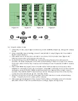
Страница 14: ... Calories for training To preset Target Distance for training OPERATION INSTRUCTION 1 When POWER ON LCD will fully display for 2 seconds Figure 1 accompanied by a long beep sound then display the wheel diameter of 78 Figure 2 before going into Standby mode 2 The CHAMPION window is always displayed SPEED TIME CALORIE DISTANCE RPM WATTS will flash in sequence Figure 3 Figure 9 If no RPM signal or pu...

Страница 15: ... will automatically go into Standby mode When checking heart rate while in Stop mode PULSE window will display user s actual pulse 65 85 or MAX Pulse value alternates accordingly Figure 12 Figure 13 3 2 Target TIME mode In Standby mode press Target Time key and TIME will light up accompanied by a long beep sound The TIME value will be flashing press UP and DOWN to adjust Figure 14 Press QUICK STAR...

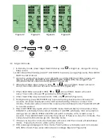
Страница 16: ...the LCD will be flashing If there is no input for 5 minutes the buzzer will sound and the console will enter Sleep mode Press QUICK START to resume the workout Press STOP RESET key again when in PAUSE mode TIME will display total workout time DISTANCE will display total workout distance CALORIES will display total calories burned during the workout WATTS SPEED and RPM will switch to display AVG MA...

Страница 17: ... and the console will enter Sleep mode Press QUICK START to resume workout Press STOP RESET key again when in PAUSE mode TIME will display total workout time DISTANCE will display total workout distance CALORIES will display total calories burned during the workout WATTS SPEED and RPM will switch to display AVG MAX every 5 seconds Press QUICK START to resume the workout If there is no input for 2 ...

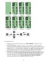
Страница 18: ...l display total workout time DISTANCE will display total workout distance CALORIES will display total consumption during workout WATTS SPEED and RPM will switch to display AVG MAX every 5 seconds Press QUICK START to resume the workout If there is no input for 2 minutes the computer will automatically go into Standby mode If there is no input for 5 minutes the buzzer will sound and the console wil...

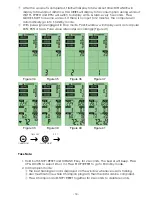
Страница 19: ...0 DISTANCE CALORIES WATTS SPEED RPM will calculate workout value In this mode you cannot press the STOP key Figure 38 When TIME counts down to 0 seconds the buzzer will sound If any value of WATTs DISTANCE and CALORIES exceeds the existing value in the computer the value will flash on screen with the readout Break the record You are the top one in ranking Figure 39 Buzzer will beep for 10 seconds ...

Страница 20: ...indow will display user s actual pulse 65 85 or MAX Pulse value alternates accordingly Figure 41 Take Note 1 Hold both STOP RESET and DISTANCE key for 2 seconds The buzzer will beep Press UP DOWN to select km or ml Press STOP RESET to go to Standby mode 2 In Champion mode The best training record is displayed on the window whenever user is training User must finish one whole Champion program then ...

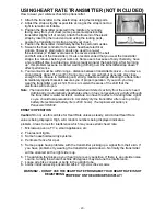
Страница 21: ...iately against bare skin assures you of proper operation If you wish you may wear the transmitter over a shirt To do so moisten the areas of the shirt that the electrodes will rest upon Note The transmitter is automatically activated when it detects activity from the user s heart Additionally it automatically deactivates when it does not receive any activity Although the transmitter is water resis...

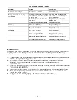
Страница 22: ...NANCE The safety and integrity designed into the air bike can only be maintained when the air bike is regularly examined for damage and wear Special attention should be given to the following 1 Pedaling slowly and verify that the Air Resistance System provides tension The Air Resistance System should provide many years of use 2 Use a wrench to verify that the pedals are tightened securely If tight...

Страница 23: ... D2 G A37 A39 A43 J6 8 A41 A42 H1 A41 B C C1 2 C2 2 C4 C5 C3 2 B1 2 B2 2 B3 2 B4 2 B5 2 B6 4 A40 A40 A4 A75 A76 A77 A78 A79 A3 I A10 A11 A12 A13 A14 A15 A16 A16 A17 A17 A18 A18 A5 A19 A30 A20 A6 A22 A23 A24 A25 A26 A27 A28 A29 A31 A80 A32 A34 2 E E2 E1 J1 J2 2 J5 6 J3 J4 F F1 A38 H2 A8 J7 2 A7 I G A68 A70 A71 A35 2 A52 A73 A73 A74 A52 A82 A36 2 A67 22 ...

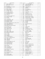
Страница 24: ...6 20mm 1 A23 SCREW M6 12mm 6 A76 STEEL 4 A24 SLEEVE 19 12 05 50 3 1 A77 PAD 1 A25 BEARING 6001 2 A78 BRAKE PAD 2 A26 SPACER RING 1 A79 SPRING 1 A27 AXLE 12 155 1 A80 SCREW M6 10mm 2 A28 PLASTIC PIPE 1 A81 SENSOR WIRE 150mm 1 A29 PLASTIC PIPE 1 A82 PLASTIC COVER 1 A30 SENSOR WIRE 750mm 1 B FRONT STABILIZER 1 A31 BUSH 10 43 2mm 1 B1 END CAP 2 A32 FIX GRIP 1 B2 WHEEL 2 A33 HOLDER 1 B3 SCREW M8 40 2 A...

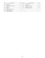
Страница 25: ...PTION Q TY J1 SCREW M8 60mm J2 SCREW M8 30mm F CONSOLE 1 J3 SPACER RING 2 F1 SCREW 4 J4 NUT M8 2 G FOOT SUPPORT 2 J5 SCREW M6 12mm 6 H1 PEDAL L 1 J6 SCREW M10 20mm 8 H2 PEDAL R 1 1 1 J7 2 I METAL FIXING PLATE 2 SCREW M6 8mm 100mm 24 ...

Страница 26: ...take MVo2 This is often referred to as your aerobic capacity The effort that you can exert over a prolonged period of time is limited by your ability to deliver oxygen to the working muscles Regular vigorous exercise produces a training effect that can increase your aerobic capacity by as much as 20 to 30 An increased MVO2 indicates an increased ability of the heart to pump blood of the lungs to v...

Страница 27: ...u stop exercising or do not do your program often enough you will lose the benefits you have gained Regular workouts are the key to success Warm Up Every exercise program should start with a warm up where the body is prepared for the effort to come It should be gentle and preferably use the muscles to be involved later Stretching should be included in both your warm up and cool down and should be ...

Страница 28: ...ir of gym or running shoes or sneakers Breathing During Exercise Do not hold your breath while exercising Breathe normally as much as possible Remember breathing involves the intake and distribution of oxygen which feeds the working muscles Rest Periods Once you start your exercise program you should continue through to the end Do not break off halfway through and then restart at the same place la...

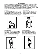
Страница 29: ...m until they are over your head Reach your reach behind you and pull your right foot up right arm as far upward toward the ceiling as Bring your heel as close to your buttocks as you can for one count Feel the stretch up possible Hold for 15 counts and repeat with your right side Repeat this action with your left foot up left arm STRETCHING Stretching should be included in both your warm up and co...

Страница 30: ...nts can and hold for 15 counts HAMSTRING STRETCHES CALF ACHILLES STRETCH Sit with your right leg extended Rest the sole of Lean against a wall with your left leg in front your left foot against your right inner thigh Stretch of the right and your arms forward Keep toward your toe as far as possible Hold for 15 counts your right leg straight and the left foot on the Relax and then repeat with left ...

Страница 31: ...her than original Dyaco Canada Inc parts or external causes such as corrosion discoloration of paint or plastic alterations modifications abuse misuse accident improper maintenance inadequate power supply if applicable or acts of God 4 Products with original serial numbers that have been removed or altered 5 Products that have been sold transferred bartered or given to a third party 6 Products tha...

Страница 32: ......

Страница 33: ......

Страница 34: ......

Отзывы: