69
en
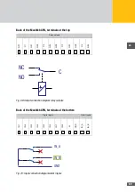
Back of the MaxWeb XPN, terminals at the top
Relay outputs
NC1
C1
N
01
NC2
C2
N
02
NC3
C3
N
03
NC4
C4
N
04
2
1
3
4
5
6
7
8
9
10
11
12
NC
C
NO
Fig. 69: Output connection diagram relay outputs
Back of the MaxWeb XPN, terminals at the bottom
Digital inputs
Alarm inputs
IN
1
IN
2
IN
3
IN
4
IN
5
IN
6
IN
7
IN
8
V+
G
ND
IN_
A
IN_
B
2
1
3
4
5
6
7
8
9
10
11
12
IN_A
IN_B
GND
Fig. 70: Input connection diagram alarm inputs
Содержание MaxWeb XPN
Страница 1: ...Installation instructions MaxWebXPN...


